


Brake 'Feel' Measured
Page 90
If you've noticed an error in this article please click here to report it so we can fix it.
MOST power-braking systems give a proportional reaction on the pedal to indicate the braking force being applied. But there are so many Variable braking factors that an indication of applied force does not necessarily give a true impression of the degree of retardation. A device which does indicate retardation is the subject of patent No.
827,323. (Clayton Dewandre Co., Ltd., Titanic Works, Lincoln.)
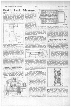
The drawing shows a typical powerbraking layout with the pedal-operated master cylinder (I) working the brakes through an auxiliary hydraulic cylinder (2). Power, assistance is provided by a vacuum servo (3), the operation of which is under the control of a valve (4). This unit imparts the usual reaction force to the pedal.
The device covered by the patent is a swinging pendulum (5) which modifies the reactive force. During deceleration, the pendulum swings forwards, causing resistance at the pedal to increase. As the pendulum swings freely, it can work in either direction. The specification gives another drawing showing the interior construction of the pendulum valve.
COMPACT COOLING SYSTEM
PATENT No. 828,014 shows an oil engine with four exhaust valves for each cylinder. All four valves are located in the cylinder head, with the injector, leaving little room for cooling passages. The subject of the patent is a compact arrangement of the water cavities. (F oden s.
Ltd., E. Twemlow and J. Mills, all of Elworth Works, Sandbach, Cheshire.) The drawing shows a section of a cylinder which is provided with the usual lower water-jacket (I). The water rises through eight holes (2) in the cylinder liner to reach a chamber (3) surrounding the exhaust-valve ducts.
Above this is a second chamber (4) and the water reaches this through a single central aperture (5) in the centre of which the injector is located. From the upper chamber the water passes to the main exit pipe (6).
SEMI-TRAILER COUPLING • PATENT No. 827,185 describes a 1 semi-trailer coupling gear which overcomes the tendency for the front wheels of the tractor to lift under maximum tractive effort when' the trailer is fully loaded. (W. Harkort, Gut Schede, bei Wetter, Ruhr, Germany.) The drawing shows a complete articulated vehicle embodying the invention. A longitudinal pull-bar (1) is located near
the axle centres. This, when tractive effort is applied, is in almost-pure tension and does not create any vertical forces.
In addition, the normal turntable (2) is mounted on a beam (3) universally pivoted on the tractor at the point 4. This enables the turntable to rise or fall with the springs of the trailer. Sideways movement of the beam is constrained by a pair of guide rails.
TORIC TRANSMISSION
THE tonic type of transmission is infinitely variable and relies for its action on friction. Patent No. 827,608 describes a means of increasing the load capacity of the gear by the use of more friction members. (C. Kraus, 100 Edgemoor Road, Rochester, New York, U.S.A.).
Referring to the drawing, the input shaft (1) is connected to the central pair of tone discs (2). The outer pair (3 and 4) are joined and drive the output shaft.
The drive is transmitted via friction rollers (5). In earlier schemes, one of these has been used, but in this case' three are employed to triple the load capacity. In the position illustrated, the device is in a low gear, because the rollers are bearing on a small driving diameter (6) and on a targer driven one (7). Tilting of the rollers about their pivot pins (8) causes the ratio to alter.
The patent states that by suitable arrangement of the pivot assemblies, the rollers can be made to precess in one direction under light load and in the other when the load increases, to give , automatic action. • The methods by which this is achieved are shown in detail in the specification.
SPACE-SAVING DISC BRAKE
PAA DISC brake described in patent No. 826,812 achieves compactness by incorporating its actuating mechanism inside the discs. It is suitable for heavy vehicles. (H. Klaue, Christophstrasse 19, Uberlingen/Bodensee, Germany.)
The brake employs two discs which expand against the sides of a drum which encloses them. In the drawing, the discs (1 and 2) are separated by a number of balls (3). The balls are located in recesses from which extend sloping ramps, so that a slight rotation of one disc relative to the other causes the balls to ride up the slope and spread both units.
The rotation is produced by hydraulic cylinders (4), each of which contains a pair of opposed pistons. Each piston pushes one of the discs tangentially when pressure is applied. The hydraulic cylinders are placed inside the discs.
BALL-BEARING SPLINES
DATENT No. 827,138 from General
Motors Corp., Detroit, Michigan, U.S.A., describes a splined shaft for driving independently sprung wheels. The splines are of ball-bearing type with inner and outer splines to provide a continuous circulating path for the balls.