


Patents Completed.
Page 28
If you've noticed an error in this article please click here to report it so we can fix it.
HYDRAULIC CLUTCH.—Hann.—No. 19,211, dated 28th August, 1906.—According to this invention, two members are arranged to rotate co-axially at the same, or at different, speeds by varying the friction between one of the members and a mass of fluid carried round by the rotation of the other member. The driving shaft (J1), on which is mounted one member of the clutch (jI), has a disc (E) secured thereto. This disc is enclosed by a casing (B) which is integral with theother member (j2) of the clutch, and is mounted freely on the shaft (J1). Between the disc (E) and the casing (B), is an annular space (A) which contains an incompressible fluid—such as oil. The casing (B) has members (D) which project into the annular space, and serve to prevent the fluid from flowing freely. Arranged within the disc (E) are members (E1) arranged to project into the annular space, and operated by means of a ratchet (F) secured to the driving shaft (j1). It will be seen that, by advancing the projections (El) into the annular space, or withdrawing the same, the friction will be reduced, or increased, and so a variable speed will be obtained.
RESILIENT TIRE. — Clew. — No. '27,523, dated 3rd December, 1906.— Flanges (F) are secured to the rim (A) of a wheel, by means of bolts (E), to form dove-tail channels. Wooden tread blocks (D), having indiarubber cushions (C) be tween them and the rim, are secured between the flanges.
CARBURETTERS.—Shiels and Others. —No. 19,711, dated 4th September, 1906. —This carburetter is intended for use with paraffin, or other hydrocarbons. The liquid fuel is supplied from the fluid chamber (E) to a fuel chamber (Cl). Projecting through the lower end of the casing (G) is the air-supply pipe (B1) through which air is supplied under pressure, the supply pipe being controlled by a valve (B2), and terminating in the air chamber (B). This chamber is formed with a plate (B3) made integral with the air supply pipe (131), and it has a top cover (H). Fuel tubes (A) are secured to the plate (BS), and project up through the air chamber (B) terminating in orifices (H1) in the top cover (H). Funnels (C) are placed over each atomising device, which consists of the tubes (A) and orifices (H1) supported in a diaphragm (G2). An air space is provided between the air chamber and the walls of the fuel chamber (D1), so that air which passes from the upper end of the fluid chamber is introduced up the funnel (C) by the mixture issuing from the spraying device, and this supplies a further body of air for the mixture. The main part of the casing K1) has a jacket, an air-space (G3) being provided, into which air enters after passing through the automatic regulator ID)heated air enters the automatic regulator by the opening (DI) and enters the air space (C3) by an opening (1)2).
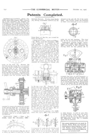
CRANK?, HA FT.—Spyker.—No 8,439, dated 11th April, 1907.—The crank-shaft is composed of crank pus i 2, 3, 4) and crank arms (5, 6, 7, 8, 9). The crank arms (5, 9, 8) arc. in the form of circular plates. or discs, the centres of which are situated in the axis (10, 10) of the crankshaft. The circular plates are hollowed on their circumferences so as to present paths (11) for ball bearings. The rings (12, 13, 14) are carried by the gear case.
VARIABLE SPEED GEAR.—SainteClaire.—No, 2,392, dated 30th January, I907.—According to this invention, the driving shaft (A) has pinions (B, C)
mounted fast upon it, and it transmits rotary motion through the gear wheels (D, E, I, .1), and pinions (J, G, K, L), to the differential wheel (II). The gear wheels (I, J) and the pinions (K, L) are mounted fast on the shafts (M, N), and the gear
wheels F), and pinions (F G) are free to slide thereon. It will be seen that, by sliding either of the gears, by means of the operating levers (X), into engagement with the driving shaft (A), and the differential wheel (H), a variable speed will be obtained.