 1
1 2
2 3
3 4
4 5
5 6
6 7
7 8
8 9
9 10
10 11
11 12
12 13
13 14
14 15
15 16
16 17
17 18
18 19
19 20
20 21
21 22
22 23
23 24
24 25
25 26
26 27
27 28
28 29
29 30
30 31
31 32
32 33
33 34
34 35
35 36
36 37
37 38
38 39
39 40
40 41
41 42
42 43
43 44
44 45
45 46
46 47
47 48
48 49
49 50
50 51
51 52
52 53
53 54
54 55
55 56
56 57
57 58
58 59
59 60
60 61
61 62
62 63
63 64
64 65
65 66
66 67
67 68
68 69
69 70
70 71
71 72
72 73
73 74
74 75
75 76
76 77
77 78
78 79
79 80
80 81
81 82
82 83
83 84
84 85
85 86
86 87
87 88
88 89
89 90
90 91
91 92
92 93
93 94
94 95
95 96
96 97
97 98
98 99
99 100
100 101
101 102
102 103
103 104
104 105
105 106
106 107
107 108
108 109
109 110
110 111
111 112
112 113
113 114
114 115
115 116
116 117
117 118
118 119
119 120
120 121
121 122
122 123
123 124
124 125
125 126
126 127
127 128
128 129
129 130
130 131
131 132
132 133
133 134
134 135
135 136
136 137
137 138
138 139
139 140
140 141
141 142
142 143
143 144
144 145
145 146
146 147
147 148
148 Self-energizing Brakes QELF-SERVO brakes depend on the " coefficient of
Page 112
If you've noticed an error in this article please click here to report it so we can fix it.
friction; if this is high, they will lock themselves on, or if it is low, a falling-off will occur in the servo action. Patent No. 832,044 describes a self-energizing brake that is claimed to be independent of the coefficient of friction. (Daimler-Benz A.G., StuttgartUntertiirkheim, Germany.)
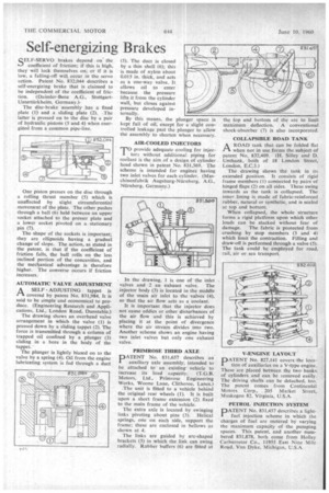
The disc-brake assembly has a fixed plate (1) and a sliding plate (2). •The latter is pressed on to the disc by a pair of hydraulic pistons (3 and 4) when energized from a common pipe-line.
One piston presses on the disc through a rolling thrust member (5) which is unaffected by slight circumferential movement of the plate. The other pushes through a ball (6) held between an upper socket attached to the presser plate and a lower socket pivoted on a stationary pin (7).
The shape of the sockets is important; they are ellipsoids having a gradual change of slope. The action, as stated in the patent. is that if the coefficient of friction falls, the ball rolls on the less inclined portion of the concavities, and the mechanical advantage is therefore higher. The converse occurs if friction increases.
AUTOMATIC VALVE ADJUSTMENT A SELF ADJUSTING tappet is r -t covered by patent No. 831,984. It is said to be simple and economical to produce. (Engineering Research and Applications, Ltd., London Road, Dunstable.)
The drawing shows an overhead valve arrangement in which the valve (1) is pressed down by a sliding tappet (2). The force is transmitted through a column of trapped oil confined by a plunger (3) sliding in a bore in the body of the tappet.'
The plunger is lightly biased on to the valve by a spring (4). Oil from the engine lubricating system is fed through a duct (5). The duct is closed by a thin shell (6); this is made of nylon about 0.015 in. thick, and acts as a one-way valve. It allows oil to enter because the pressure lifts it from the cylinder wall, but closes against pressure developed internally.
By this means, the plunger space is kept full of oil, except for a slight controlled leakage past the plunger to allow the assembly to shorten when necessary.
AIR-COOLED INJECTORS
T° provide adequate cooling for injectors without additional piping for coolant is the aim of a design of cylinder head shown in patent No. 831,569. The scheme is intended for engines having two inlet valves for each cylinder. (Maschinenfabrik Augsburg-NUrnberg, A.G., Nilrnberg, Germany.)
In the drawing, 1 is one of the inlet valves and 2 an exhaust valve. The injector body (3) is located in the middle of the main air inlet to the valves (4), so that the air flow acts as a coolant.
It is important that the injector does not cause eddies or other disturbances of the air flow and this is achieved by placing it at the point of divergence where the air stream divides into two. Another scheme shows an engine having two inlet valves but only one exhaust valve.
PRIMROSE THIRD AXLE
DATENT No. 831,657 describes an auxiliary axle assembly, intended to be attached to an existing' vehicle to increase its load capacity. (T.G.B. Motors, Ltd., Primrose Engineering Works, Woone Lane, Clitheroe, Lancs.) The unit is fitted to a vehicle behind the original rear wheels (1). It is built upon a short frame extension (2) fixed to the main frame of the vehicle.
The extra axle is located by swinging links pivoting about pins (3). Helical springs, one on each side, support the frame; these are enclosed in bellows as shown at 4: The links are guided by arc-shaped brackets (5) in which the link can swing radially. Rubber buffers (6) are fitted at the top and bottom of the arc to limit maximum deflection. A conventional shock-absorber (7) is also incorporated COLLAPSIBLE ROAD TANK
PIA ROAD tank that can be folded flat when not in use forms the subject of patent No. 832,409. (H. Silley and D. Unthank, both of 18 London Street, London, E.C.3.)
The drawing shows the tank in its extended position. It consists of rigid frame members (1) connected by pairs of hinged flaps (2) on all sides. These swing inwards as the tank is collapsed. The inner lining is made of fabric-reinforced rubber, natural or synthetic, and is sealed at top and bottom.
When collapsed, the whole structure forms a rigid platform upon which other loads can be stacked without fear of damage. The fabric is protected from crushing by stop members (3 and 4) which limit the contraction. Filling and draw-off is performed through a valve (5). The tank could be employed for road, rail, air or sea transport.
V-ENGINE LAYOUT
PATENT No. 827,141 covers the location of auxiliaries on a V-type engine. These are placed between the two banks of cylinders and can be removed easily. The driving shafts can be detached, too. The patent comes from Continental Motors Corp., 205 Market Street,
Muskegon 82. Virginia, U.S.A.
PETROL INJECTION SYSTEM
PATENT No. 831,457 describes a lightfuel injection scheme in which the charges of fuel are metered by varying the maximum capacity of the pumping spaces. This patent, and another numbered 831,878, both come from Holley Carburrctor Co., 11955 Fast -Nine Mile Road, Van Dyke, Michigan, U.S.A.