


Mullard's electronic anti-locking device
Page 32
If you've noticed an error in this article please click here to report it so we can fix it.
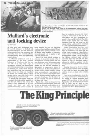
by Ron Cater • After seven years' development work, the research laboratory of Mullard Ltd, electronics specialists, last week introduced to the motoring Press what promises to be a reasonably priced and extremely effective anti-wheel-locking device for hydraulically braked vehicles.
A Mullard spokesman said at a demonstration at the Road Research Laboratory at Crowthorne , that the unit was still in a very early stage of development. However, the demonstration showed that even now the unit comes close to producing the results which designers have sought for a long time. Questioned as to the eventual cost of the unit when fitted on private cars, another Mullard official thought that the figures £50, £100 or £150 suggested by a guest, were too high.
A separate unit, only slightly larger than a standard disc-brake calliper assembly, is used for each wheel of the vehicle. The system is fully independent on all road wheels and does not rely on transmission-mounted control systems. It could therefore be used on free-roIling wheels, an important factor should Mullard apply the device to heavy vehicles. It is for the present being developed for cars only, but .could equally well be applied to light vans in its present state.
One of the most difficult problems to overcome in an anti-lock system is that of recharging the actuating cylinder with fluid once the sensing device has caused pressure to be released. In other types of anti-lock systems this task has been completed by large electric or vacuum-servo motors. In the Mullard unit the fluid released from the actuator is fed to a piston assembly, causing this to be pressed on to a cam formation on the hub. So, as soon as the wheel re-starts, the cam becomes operative, forcing the fluid back into the actuator, The lift induced by the cam is a mere 2mm and the diameter of the piston only 12mm.
Signals that a wheel has stopped turning are transmitted from a magnetic sensor and fed into an electronic circuit which, on the demonstration vehicle, was fairly large. Once in production, however, this circuit would be miniaturized to the size of a safety-match box and encapsulated to protect it from road-dirt and wet. The whole device would require only one wiring connection from the live circuit on the vehicle and the quality could be controlled to a very high level by the manufacturers.
Several illuminating exercises were carried out, the one I found most impressive being a full-pressure stop made with the offside wheels running on a low-adhesion surface and the nearside wheels running on a high-adhesion surface. The car fitted with the Mullard anti-lock made perfectly controlled stops from 30 mph with little evidence of loss of directional stability, whereas the vehicle not equipped with the device turned two complete circles on each• stop.
Stopping distances by the two vehicles under identical Conditions varied by lengths of over 100ft. and again the vehicle fitted with the device was kept under complete control.
There are no immediate plans to put the unit into production and it is not expected to be offered as original equipment until around 1974, and then at first only on high-quality cars. But there seems no reason why it could not be fitted to any hydraulically braked heavy vehicle, whether equipped with disc or drum-type brakes.