ntrolling engine nperature 3
Page 49

If you've noticed an error in this article please click here to report it so we can fix it.
1E LAST article the waxthermostat was described. 3ther variety, in common is the bellows type :rated in Figure 1, which ts its operating element a )d, flexible metal bellows, y filled with a volatile liquid as acetone or methyl
valve is attached to the top e bellows. When the engine Id, the valve is held on its by the contraction of the mis and no coolant can flow the engine to the radiator. le engine warms up, and the ant is heated, the liquid in )ellows is converted into >ur so increasing the sure in the bellows causing extend and so to open the a. The coolant can then flow past the open valve from the engine to the radiator.
As with the wax element type, described in the last article, a bypass provides limited circulation around the water passages when the thermostat is closed.
In addition, the thermostat valve contains a small bleed hole which provides some circulation when the valve is closed and prevents air locks occurring when the cooling system is being filled. Generally there is a jiggle pin fitted in the bleed hole.
Thermostats may be tested by immersing them in hot water, and then ascertaining at what temperature the thermostat opens. Special rigs with an electric element for heating the water and a tray in which to rest the thermostat are available for this purpose.
One of the disadvantages of using water as a coolant is that its boiling point is lower than the temperature at which an engine operates efficiently. The complicated design of cylinderhead water jackets gives rise to a risk of local steam pockets forming at critical positions, for example around the exhaust valve seats. Steam is a poor conductor of heat and should be eliminated from the system.
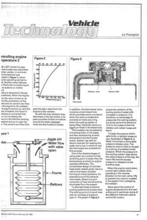
To alleviate these problems cooling systems are pressurised. The boiling point of a liquid rises with an increase of pressure upon it. The graph in Figure 2
shows the variation of the boiling points of water with increases in pressure. It is, therefore, an advantage to pressurise the cooling system, but at the same time there is a limit to the pressure that the radiator and rubber hoses will stand.
To keep the presure within safe limits, a radiator pressure cap, illustrated in Figure 3, is fitted. It is simply a removable pressure release valve. The pressure valve is held on its seat by a spring of predetermined pressure. When the pressure in the cooling system rises above the rated pressure of the cap, the valve lifts and the excess pressure is released via the overflow pipe.
When the engine cools down, a small light loaded valve, operating in the reverse direction to the main valve, lifts to prevent any vacuum created in the system from collapsing the radiator.
More about the control of engine temperature in the next article and in particular some of the different methods used to control fan output.


