


. . and semi-automatic trunker
Page 65
If you've noticed an error in this article please click here to report it so we can fix it.
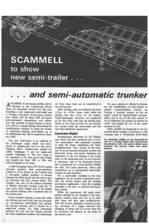
ANUMBER of interesting exhibits will be featured at the Commercial Motor Show by Scammell Lorries Ltd. this year including a new single-axle semi-trailer and a Trunker twin-steer 32-ton-gross tractive unit which will be fitted with five-speed semi-automatic transmission and splitter box. But possibly of equal interest to operators will be a special display illustrating the modifications required to bring the brakes of automatic-coupling semi-trailers up to the efficiencies that will be required in January 1968.
The new semi-trailer is an addition to the Challenger range which was introduced in tandem-axle form at last year's Glasgow Show. Tandem-axle models are called Challenger T and the single-axle models Challenger S. The new range is for operation at 22 tons gross train weight and lengths are from 24ft. to 34ft. and will be available in lft. steps.
A Self-Changing Gears RV.38 five-speed epicyclic gearbox with semi-automatic control is to be shown in the Trunker and a two-speed splitter gearbox is located between the fluid clutch and the unit to give ten forward and two reverse ratios. The Trunker was one of the earliest examples of British twin-steer tractive units for 32 tons gross train weight and in the design the second steering axle is located close to the driving axle.
Power-assisted steering is used and while the driving axle and front axle are mounted on conventional semi-elliptic leaf springs the second steering axle is located by a single-leaf spring. Air bags interposed between the axle and the chassis provide the main suspension medium. By exhausting air from these load can be transferred to the driving axle.
Both steering axles are identical and have 15.5in. by 4.25in. brake units whilst the driving axle has 15.5in. by 7in. brakes. Triple-diaphragm actuators are employed at the first front axle and the driving axle. Those at the front provide for the secondary system (with the semi-trailer) and the rear help handbrake application.
Conversion display Modifications illustrated in the display unit which will show operators how to convert semi-trailers with automatic coupling to meet the future regulations are fairly straightforward. They consist of the addition of an air-pressure-actuation system and bell-crank levers and brake chambers are interposed in the rod linkage to the brake units on the Scammell axle. An air reservoir is necessary and in the Scammell layout this is positioned on a cross member behind the axle. The usual pipework, valves and connections as in conventional semi-trailer systems are also included.
On a semi-trailer modified in the way suggested, the air system is intended to provide the service brakes and the existing mechanical application—from the coupling turntable to the axle—is used for the secondary system.
While the conversion will make semitrailers suitable for the changes in the regulations, tractive units that are to be used with them will also need modifications. This will involve, primarily, revisions in piping, provision of a bigger reservoir and changing of valves and so on but what will be necessary will depend on the make of the tractive unit.
No easy solution is offered by Scamrr for the modification of semi-trailers 1.15 behind vacuum-braked tractive uni Putting a vacuum system on the ser trailer would be impracticable because delay and so on, so the only answer is fit an additional air system on tractive ur which will largely be out of the questi because of cost.
Other exhibits by Scammell at the Co mercial Show include a Contractor, a Hii wayman and a Townsman three-wheel