 1
1 2
2 3
3 4
4 5
5 6
6 7
7 8
8 9
9 10
10 11
11 12
12 13
13 14
14 15
15 16
16 17
17 18
18 19
19 20
20 21
21 22
22 23
23 24
24 25
25 26
26 27
27 28
28 29
29 30
30 31
31 32
32 33
33 34
34 35
35 36
36 37
37 38
38 39
39 40
40 41
41 42
42 43
43 44
44 45
45 46
46 47
47 48
48 49
49 50
50 51
51 52
52 53
53 54
54 55
55 56
56 57
57 58
58 59
59 60
60 61
61 62
62 63
63 64
64 65
65 66
66 67
67 68
68 69
69 70
70 71
71 72
72 73
73 74
74 75
75 76
76 77
77 78
78 79
79 80
80 81
81 82
82 83
83 84
84 85
85 86
86 87
87 88
88 89
89 90
90 91
91 92
92 93
93 94
94 95
95 96
96 97
97 98
98 99
99 100
100 101
101 102
102 103
103 104
104 105
105 106
106 107
107 108
108 109
109 110
110 111
111 112
112 113
113 114
114 115
115 116
116 117
117 118
118 119
119 120
120 121
121 122
122 123
123 124
124 125
125 126
126 127
127 128
128 129
129 130
130 131
131 132
132 133
133 134
134 135
135 136
136 137
137 138
138 139
139 140
140 141
141 142
142 143
143 144
144 145
145 146
146 147
147 148
148 Drum-brake Cooling
Page 104
If you've noticed an error in this article please click here to report it so we can fix it.
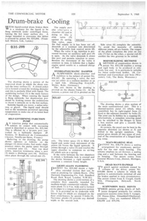
WITH liquid-cooled drum brakes there VV is a tendency for the liquid to be flung outwards under centrifugal force, leaving the hot inner surface dry. A Jesign intended to overcome this defect is covered by patent No. 835,094. (Vauxhall Motors, Ltd., Luton.) The drawing shows a section of the improved drum in which the shoes contact the inner surface (I). A closed jacket (2) is formed around the working diameter arid this is partially filled with liquid. The undulating surface (3) is the main feature of the design. When running the liquid is flung outwards, but deceleration produced by braking causes the undulations to throw it inwards on to the hot surface.
Suitable liquids are water, a saline solution or glycol. The liquid used should boil at the maximum permitted operating temperature to make use of its latent heat of evaporation.
SELF-GOVERNING INJECTION PUMP
AN injection pump that automatically reduces its output with increasing speed is described in patent No. 835,344. This is effected by a by-pass port controlled by a hydraulic dashpot. (P. Bessiere, 55 Boulevard du Commandant Charcot, Neuilly-sur-Seine, France.) Referring to the drawing, the pump shown operates as follows: on the plunger (1) down-stroke, fuel under slight pressure enters the pump space through a restricted inlet (2). Near top dead centre, injection terminates when a port
(3) meets a discharge port (4). Delivery takes place through the valved exit (5).
The supply port also charges a chamber (6) and in doing so lifts a slide valve (7) against its spring. This valve, once the fuel supply to it has been cut off, descends at a constant rate determined by the adjustable leak control screw (8).
When the valve is up, injection is prevented because an auxiliary spill port (9) is open. As the valve descends it closes this port and permits injection to occur. Because the movement of the valve is constant in time, it follows that a higher engine speed results in a reduced charge of fuel.
HYDRO-PNEUMATIC DAMPER A _ SUSPENSION shock-absorber and Pi stabilizer is the subject of patent No. 835,107. By operating a valve, the unit can act either as a resilient member or as a rigid link. (Deinag-Zug G.m.b.H., Wetter, Ruhr, Germany.)
The unit shown in the drawing is pivoted on the chassis frame (1). At the bottom, a piston rod (2) is pivoted on the axle, The lower space (3) is filled with liquid and, under load, movement of the piston (4) forces the liquid upwards. It passes through a valve (5) and reaches the upper chamber to compress an air-bag (6) which acts as a spring.
If the valve between the two chambers is closed, a hydraulic lock is created and the device becomes a rigid member to maintain a constant frame height.
LIGHT-ALLOY FLOORING
PATENT No. 835,260 shows a lightalloy extruded section that can be used as planking for vehicle floors. (The Duramin Engineering Co., Ltd., Standard Road, Park Royal, London, N.W.10.)
The drawing shows a cross-section of a complete floor assembly intended for medium-weight commercial vehicles. The main plank (I) is 9 in. wide and is formed at its edges to a tongue-and-groove section (2). It is provided on its underside with bearer legs (3) which are clamped on the floor cross-bearers by special T-bolts (4). Narrower planks (5) provideany desired width to the nearest inch. Side raves (6) complete the assembly. To avoid the necessity of making different joints, all are female. The tongue of the plank completes the joint on one side (7) but on the other, a special rod (8) enables the two grooves to be united.
BODYBUILDING SECTIONS A METHOD of construction shown in patent No. 835,138 enables a strong and rigid body to be produced at relatively low cost. It is particularly suitable for metal cattle-truck bodies. (H. Carmichael and Carmichael and Sons (Worcester), Ltd., The Butts, Worcester.) The drawing shows a plan section of the main constructional unit. This is a channel-section panel (1) which, when assembled, has its right-angled faces (2) fixed to the adjacent member by bolts (3). The joint can be hidden by a capping (4). Alternatively, a complete covering panel can be attached to the flanges to form a box section and give a smooth face on each side.
At corners, the panel can be bent in the opposite direction (as shown at 5) and bolted to the upright members. The patent gives details of two types of roof, and of the construction of a hinged loading ramp.
MAIN-BEARING SEAL pATENT No. 838,576 shows a sealing arrangement for crankcases, particularly for the rear main bearing. The scheme employs an oil thrower, a sealing ring and a seal between the bearing and its housing. The patent comes from General Motors Corp., Detroit, Michigan, U.S.A.
DEAD MAN'S HANDLE TO guard against accidents caused by 1 collapse of the driver, patent No. 839,086 shows a scheme in which the ignition is automatically switched off arid the brakes applied in such circumstances. The patent comes from S. Cargill, Garth Mill, Ffnnogroew, Holywell, North Wales.
SUSPENSION BALL JOINTS
THREE patents giving details of balljoints designed primarily for vehicle suspension systems come from V. Langen, 190 Hansa-Allee, Dfisseldorf-Oberkassel, Germany. They are numbered 838,457; 838,458 and 839,396.