


An Exhaust Braking System
Page 62
If you've noticed an error in this article please click here to report it so we can fix it.
EXHAUST throttling is a method of I—, braking that seems to have received more attention on the Continent than in this country, and it is therefore interesting to see a British company developing the scheme. The concern is Clayton Dewandre Co., Ltd., Titanic Works, Lincoln, and the design is disclosed in patent No. 732,829.
In the scheme proposed, the accelera tor pedal also operates the exhaust brake, so that the one pedal gives complete control over the speed of the vehicle.
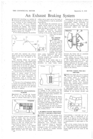
The drawing shows the general layout of the parts. The exhaust pipe (l) is fitted with a butterfly valve, which is operated by an air cylinder (2). The control valve (3) of the air supply is worked by the accelerator pedal, either directly or by the method shown.
This consists of a solenoid (4) wired to a micro-switch (5) on the heel of the pedal. A master switch is incorporated in the circuit; this enables the brake to be made inoperative in circumstances such as starting when its functioning might be an embarrassment.
In the case of an oil-engined vehicle, a second air-controlled member (6) is coupled to the rack rod of the injection pump so that the fuel is cut off while the brake is applied.
A SYSTEMATIC LOAD-STOWING SCHEME
PATENT No. 732,638 (M. Tamini, I Via G. B. Vico 38, Milan, Italy), refers to vehicles which have to carry
a load of standard containers of which full and empty ones are constantly being exchanged. The subject of the patent is a means for handling the containers so that the wanted ones are conveniently to hand at all times.
The drawing shows a van packed with 21 containers, the seven shown being repeated in two other rows. The racks carrying them are fitted with A36 rollers and at each end of the body is a lifting platform (1 and 2), preferably power-driven.
By this means the containers can be rapidly moved round in any desired order so that a full one is always to hand and space is available to receive an empty. Moreover, the scheme eliminates the need for temporarily stacking on the ground, which, in many cases, may be inconvenient.
OIL ENGINE STARTING TO assist starting an oil engine in cold weather it is a well-known practice to prime the intake with a small quantity of volatile fuel, such as ether. The priming methods are sometimes rather haphazard and patent No. 732,946 shows a scheme for ensuring complete and uniform volatilization of the ether.
Mounted in the intake pipe is a cylinder (1) made of gauze, unglazed porcelain or other finely pored
material. Through the centre is a pipe (2) leading to the outside. In the present scheme the priming charges are supplied in small sealed cylinders, one of which is shown at 3.
This is simply punctured by thrusting it onto the sharp end of the central pipe so that the charge can then permeate the gauze. The ingoing air, as it passes the soaked gauze, becomes uniformly charged with the ether.
The patent is in the name of Inertia Starter Developments, Ltd., 6 Bishopsgate, London, E.C.2.
A RUBBER ENGINE MOUNTING HAVING VARIABLE STIFFNESS
RUBBER, like all other springs, gives an increase of resistance with increase of load, but for purposes such as engine mountings the increase is often too rapid. Patent No. 732,713 (Metalastik, Ltd., Evington Valley Road, Leicester) shows a mounting fitted with a modifying element arranged so that, after a certain deflection is reached, no further increase occurs in the resistance.
Referring to the drawing, an engine (1) is attached to the frame (2) by a conventional rubber mounting (3) loaded in shear. The basis of the patent is the addition of a small precompressed rubber strut (4) held between the frame and an extension bracket (5) from the engine.
The rubber strut is shown in its central unstable position, from which it will readily move in either an upward or downward direction. The slightest deflection of the main mounting triggers off this trapped force in opposition and so creates a limiting value to the stiffness.
BETTER VISION FOR BUS DRIVERS
WHEN the engine of a bus is located, WY at the rear, the absence of radiator and bonnet makes it possible to improve driver visibility. Such an improvement forms the subject of patent No. 733,107, from Leyland Motors, Ltd., Suffolk House, Laurence Pountney Hill, London, E.C.4.
Vision through glass is always best at right-angles thereto and the proposed scheme is based on this fact. In addition to the normal off-side and
front windows, a near-side one (1) is provided. This is positioned at an angle of 45 degrees, so that when the driver looks through it his line of sight i,-; approkimately at right-angles to the glass.
Part of the window forms the door of the cab, being hinged along the edge (2). The angled window covers approximately half of the total width of the vehicle.