


Back Axle Has Positive Oil Feed
Page 60
If you've noticed an error in this article please click here to report it so we can fix it.
HITHERTO, the usual method of lubricating such a component as a back axle has been to keep the oil at a certain level and to rely on the revolving parts to provide distribution. That this is no longer considered reliable enough is the impression gained from patent No. 624,970, which shows an axle fitted with a definitely pumped lubricating system.The patentees are F. Cowell and Kirkstall Forge, Ltd., both of Kirkstall Forge, Leeds.
On the end of the bevel pinion is formed a small eccentric (I). This makes contact with a pump plunger (2) of simple design, which draws oil from the lowest part of the casing and delivers it in a series of jets from nozzle (3). In positioning the jets, particular attention is given to those responsible for feeding those bearings which normally suffer most from lack of oil. A passage (4) is also connected to the pump; this leads to the bevelpinion bearings (5), which are usually the first to fail When the oil level gets low.
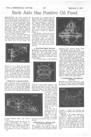
A RESILIENT CAB-MOUNTING
AN improved resilient mounting for the cab of a:lorry is shown by the Ford Motor Co., Ltd., 88, Regent Street, London, W.1, in patent No. 620,280 The aim is to prevent twisting stresses in the frame from reaching the cab and
causing jammed doors and similar troubles.
The drawing shows one side of the chassis . side-member (1) which is strengthened to receive a bolted-on bracket carrying a wedge-shaped rubber block (2). The cab is carried on a cross-member (3) which is coupled to A34 the bracket by a swinging link (4) fitted with rubber bushes round its pivots. Thus a complete rattle-free anti-twist 'suspension is provided, the resilient member being the rubber block which resists motion in one direction but is free in the other.' The scheme is employed only at the rear end of the cab; the front is fixed by ordinary means.
The efficiency of this type of cab mounting was tested with a vehicle carrying a full payload. A jack was placed under the near-side front wheel, which was raised until the off-side wheel was clear of the ground. Even with the frame twisted to this extent the doors did not jam.
A TRACTOR FROM FRANCE
PATENT No. 624,059 comes from G. Thomas, Paris, and shows a new design for an agricultural tractor. Whilst conventional in many ways, the machine nevertheless possesses many novel features.
The drawing shows a side elevation with two of the wheels removed. The machine normally runs with the two large driving wheels leading, and these carry the weight of the engine and the transmission. The rest of the frame is articulated about an axis passing through the front axle on a pair of trunnions (1). Steering is performed by selective clutching and braking of the driving wheels, the driver's control being a pair of levers (2).
The rear axle is pivoted about a horizontal bar (3) so that it can follow the irregularities of the ground. A splined shaft (4) is provided for use as a power take-off.
DIFFERENTIAL DEVICE FOR BATTERY-ELIECTRICS
TO. replace the standard type of differential is the aim of a scheme shown in patent No. 624,109, by Victor
Electrics, Ltd., Victoria Street, Burscough Bridge, Lancs., and others.
The drive is connected directly to one rear wheel, and the other is connected through the clutch shown in the drawing; this is housed in the position usually occupied by the differential.
The outer drum member (1) is connected to the wheel not normally driven, whilst the innermost shaft (2) drives the other wheel. The driving torque is applied by the crown-wheel to a shoecarrying plate. (3) which drives the fixed wheel via leaf-springs (4) gripping a. cam (5). Under light load the cam transmits the drive with little displacentept, but if a heavier load be applied, it turns slightly, forces the shoes (6) against the outer drum and so applies a drive to the other wheel.
A WINDSCREEN DE-MISTING DEVICE
FROM the Austin Motor Co., Ltd., and G. Parker, both of Northfield, Birmingham, comes patent No. 622,465,
showing a means for heating the interior of a vehicle and de-misting the windscreen.
Adjacent to the exhaust manifold is a bolted-on heater box (1) which receives air from a forward-facing funnel (2). After being heated in the box, the air passes through a control valve (3) which proportions the flow between a duct leading to the interior and one or more de-misters (4). These feed hot air to the inner side of the screen and so prevent the formation of mist.