


A NOVEL SUPERCHARGING ENGINE.
Page 32
If you've noticed an error in this article please click here to report it so we can fix it.
A Résumé of Recently Published Specifications.
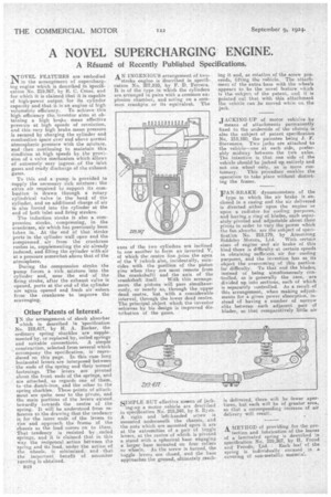
NTOVEL FEATURES are embodied IN in the arrangement of supercharg• ing engine which is described in specification No. 219,567, by R. C. Cross, and for which it is claimed that it is capable of high-power output for its cylinder capacity and that it is an engine of high volumetric efficiency. To achieve this high efficiency the inventor aims at obtaining a high biAlce mean effective pressure at high speeds of revolution, and thisvery high brake mean pressure is secured by charging the cylinder and combustion space over and above normal atmospheric pressure with the mixture, and then .continuing to maintain this condition at high speeds by the 'provision of is valve mechanism which allows of extremely easy ingress of the inlet gases and ready discharge of the exhaust gases.
To this end a pump is provided to supply the necessary rich mixture: the extra air required to support its combustion is drawn through a rotary cylindrical valve in the head of the cylinder, and an additional charge of air is also forced into the cylinder at the end of both inlet and firing strokes.
The induction stroke is also a compression stroke, compressing, in the crankcase, air which has previously been taken in. At the end of that stroke ports in the cylinder wall open and the compressed air from the crankcase rushes in, supplementing the air already induced, and filling the cylinder with air at a pressure somewhat above that of the atmosphere.
During the compression stroke the pump forces a rich mixture into the cylinder and, near the end of the firing stroke, after the exhaust valve is opened, ports at the end of the cylinder are again opened and fresh air enters from the crankcase to improve the scavenging:
Other Patents of Interest.
IN the arrangement of shock absorber which is described in 'Specification No. 219,417, by H. A. Becker, the ordinary spring shackles. are supple
mented by, or replaced.by, coiled springs and suitable connections. A simple
construction.' selected from several which accompany the specification, isreproduced on this page. In this case long horizontal levers are Interposed between the ends of the spring and their normal fastenings. The levers are pivoted about the front ends of the springs-, and are attached, as regards one of them, to 'the dumb-iron, and the other to the spring shackles. These points of attachment are quite near to the pivots, and the main portions of the levers extend inwardly towards the centre of the spring. It will be understood from reference to the drawing that the tendency is, for the inner ends of the lever to rise and approach the frame of the chassis as the load comes on to them. That tendency is resisted by coiled springs, and it is claimed that in this way the reciprocal .action between the spring and its load, under the action of the wheels, is minimized, and that the important benefit of smoother sunning is obtained.
848
AN INGENIOUS arrangement of two
stroke engine is described in specification No. 207,810, by F. D. Ferrera. It is of the type in Which the cylinders are arranged in pairs with a common explosion chamber, and acting on a common crankpin or its equivalent. The axes of the two cylinders are inclined to one another to form an inverted V, of which the centre line joins the apex of the V (which also, incidentally, coincides with the position of the piston pins when they are most remote from the crankshaft) and the axis of the
crankshaft itself. With this arrangement the pistons will pass simultaneously, or nearly so, through the upper dead centre, but with a considerable interval, through the lower dead centre. The principal object which the inventor achieves by his design is improved distribution of the gases.
SIMPLE BUT effective means of jack ing-up a motor vehicle are described. in specification No. 219,248, by S. Ryan.
right and left-handed screw is mounted underneath the chassis, and the nuts which are mounted upon it are at the extremities of a pair of toggle levers, at the centre of which is pivoted a stand with a spherical base engaging a 'larger base mounted on four rollers or wheels. As. the screw is turned, the toggle levers are closed, and the base approaches the ground, ultimately reach
ing it and, as rotation of the screw proceeds, lifting the vehicle. The attachmentof the extra base with the wheels appears to be the novel feature which is the subject of the patent, and it is pointed out that with this attachment the vehicle can be moved while on the jack.
JACKING-UP of motor vehieies by means of attachments permanently fixed to the underside of the chassis is also the subject of patent specification No, 219,180, the patentee being J. F. Stevenson. Two jacks are attached to the vehicle—one at each side, preferably midway between the two axles. The intention is that one side of the vehicle should be jacked up entirely and not one wheel only, as is more cus tomary. This procedure enables the operation to take place without distorting the frame.
FAN-BRAKE dynamometers of the type in which the air brake is enclosed in a casing and. the air delivered is directed either upon the engine or upon a radiator for cooling purposes, and having a ring of blades, each separately pivoted and adjustable about their pivots in order to vary the power which the fan absorbs, are the subject of specification No. 219,179, by Armstrong Siddeley Motors, Ltd. With certain sizes of engine and air brake of this kind there is difficulty' at certain speeds in obtaining sufficient air for cooling purposes, and the invention has as its object the overcoming of this particular difficulty. To that end the blades, instead of being simultaneously con-trolled, as is generally the case, are divided up into sections, each of which is separately controlled. As a result of this arrangement, when making adjustments for a given power absorption, instead of having a number of narrow slits between each adjacent -pair of blades, so that comparatively little air is delivered, there will be fewer apertures, but each will be Of greater area, so that a corresponding increase of air delivery will result.
A. METHOD of providing for the protection and lubrication of the leaves of a laminated spring is described in specification No. 219,367, by H. Frood
and Ferodo, Ltd. Each leaf of the spring is individually encased in a covering of non-metallic material.