


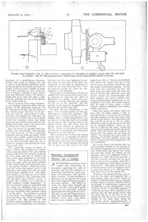
THE CARSAFE LOAD GOVERNOR. •
Page 18
Page 19
If you've noticed an error in this article please click here to report it so we can fix it.
An Ingenious American Device for Preventing Overloading.
rr'l HE two pincipal causes of rapid
wear in commercial vehicle chassis are overdriving and Overloading, and I think it may be stated as an axiomatic fact that, if these two oviLs could be eliminated, motor vehicles would run twice as long as they now do without need for repair.
So far as checks against overdriving are concerned, we have many, in the shape of registering speed indicators and speed governors, though whet-her either of them is used as generally as is desirable is open to doubt; but, until the advent of the device I am now about to describe, no effort so far as I am able to recall had been made to prevent overloading.
All who are acquainted with the working of trade motor vehicles are well aware that, not only drivers but. owners also, are far too prone to ignore the load capacity for which their cars are built; but, so long as the body will hold them, often cram on all the goods they can get into it regardless of their aggregate dead weight. Besides this, many do not know the actual weights they are carrying.
In trades in which deliveries are made in standard packages of a single product, it is easy to limit the loads by the number of packages carried, but in businesses of a miscellaneous character, dealing with goods of .varying size and weight, it is not usually feasible to weigh up all parcels to be carried and load by weight, and it is more a matter of guess work than anything to know when the load is enough, although a really intelligent and observant driver will obtain a rough idea as to when the load is sufficient by watching the set of the springs as the load is put on.
This is, however, but a rule-of-thumbor eye—method, and must differ with the powers of the individual observer and his interest in his job, and the object a the Carsafe Load Governor is to provide not only an exact means of auto' matically ascertaining the load that has been put on a vehicle, but a 'sound signal which will instantly advise the loader when the safe load has been reached and, further than this, which will prevent the car being run when overloaded.
This new device is operated both electrically and hydraulically, and embodies • two basic features ; to wit, a hydraulic reduction between load and gauge which reduces the needful weight of all parts of the mechanism, and a device to cut out the load governor when the car or vehicle is running and prevent its registering road jolts.
The • registering device is shown in Figs. 1 and 2, and consists of a casting which takes the place of the usual spring shackle, and has to be specially designed for each make and size of vehicle ; all other parts being Standard for all kinds and sizes. The device is made in two parts, the upper part (A) being attached to the i-hassis frame and taking the place of the spring bracket, whilst the lower part (B) carries the spring bolt (0) and attaches to the spring eye, the two parts being hinged together at D. The upper part carries an oil reservoir (E) in direct reduced connection with a.Bourdon tube, and the lower part carries a tread, or plunger (F), working in • it through a solid welded-in bronze diaphragm. To the uninitiated it may be explained that the action of a Bouiden tube is as follows :—The tube is Curved and closed at one end, and fluid under pressure enters it at the other. As pressure is exerted on the fluid, the tendency . of _ the fluid (and,, therefore' the tube). is slightly to straighten out, 'the aniount of this tendency. varying clirectV withethe pressure 'exerted.COnSequently, by araanging • the short end of a lever indicator in contact with the free end of the tube, any movement of the tube is registered on a dial by the long end of the lever. Most air pressure gauges for tyres are constructed on this principle. The operation of the device will thus be readily followed, and it will be seen that, as increase of load has the effect of flattening the spring, more and more pressure 1.9 exerted through the plunger on the oil in the reservoir, and the amount of the pressure is registered on the dial (0) by the finger (H).
So much for the registration of the load. The electrical feature of the construction now comes into operation. The gauge (G), as is shown in Fig. 2, is furnished with a 'circuit-closing device (J), so located on the dial that it is reached by the pointer (H) when the load on the spring reaches the safe limit, and the action which follows is indicated in Fig. 3. Either a one-wire or a two-wire circuit may be employed, the illustration showing a two-wire device.
What happens now is that the closing of the circnit at 3' energizes the electromagnet (K), and the armature (L) is instantly attracted, in its turn withdrawing the catch (M), which permits the spring (N) to pull over the end of the bell crank lever (0), to which it is attached. This allows the copper ball (I) to fall and so opens the ignition circuit (Qs, and the engine is prevented running. At the same time the movement of lever (0) pulls away the metal plate (R) from the contact brushes (S), and this opens the circuit around the electro-magnet (K), both ignition and control circuits thus being simultaneously opened and, as the operation is so brief, the electro-magnet may be made to carry quite a heavy current without exhausting the battery which operates it.
When the spring (N) draws back the lever (0), the latter strikes a bell, so that the driver is warned of the overload, and the ignition circuit stays open until closed by the driver, who mast then pull the rod (T) as far as it will go, which affews the cable to pull the lever (0) back to its original position, where on one side it is held by the catch, whilst the copper ball is raised and circuit (9) closed by it, and the driver has perforce to reduce his load before he can start his engine. By making the pull-rod (T) interlocking with the ignition switch the driver is prevented from tampering with the mechanism.
Up to this point it is obvious that the extra pressure elected on the springs by the action of passing over a road obstruction would bring the device into action and stop the engine by cutting off the ignition, and -soan additional device is adopted, by which the load governor is cut out of action directly the car starts and so long as it is running; and this is done by means of a little. speed governor, shown at U. This speed governor is set so that as Soon as the car begins to move it opens the circuit at V, which is otherwise kept closed by the spring (W).
Originally this speed governor was carried on the dash and *rated like a speedometer from one of the wheels by means of a flexible shaft, but as objection is often taken to the use of flexible shafts. on account of complication, expense ana unreliability, a new arrangement, which is shown in fig. 4, has been adopted, in which the governor (3) is attached to the steering arm (4), and geared direct with the gear ring (1) on the hub (5) by the pinion (2), and the power conveyed electrically to the dash, upon which the mechanism showft diagrammatically iii Fig. 3 is mounted, enclosed in a neat box.