


Patents Completed.
Page 22
If you've noticed an error in this article please click here to report it so we can fix it.
Austin Cam-operated Sleeve Valve. Sankey Sheet-metal Wheels. Interesting Lubrication System. Automatic Change-speed Gearbox.
Copies of complete specifications of the patents published on this page can be obtained from the Sales Branch, Patent Office, Holborn, WC, at the cost of sixpence for each specification.
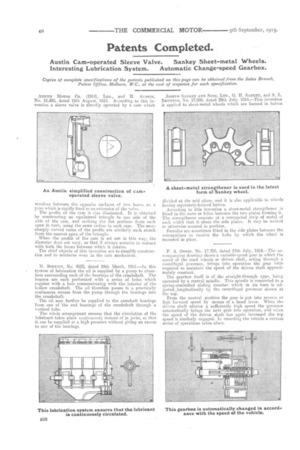
AUSTIN MOTOR CO. (1914), LTD., and IL AUSTIN, No. 18,485, dated 10th August, 1914. According to this invention a sleeve valve is directly operated by a cam which
revolves between the opposite surfaces of two horns on a yoke which is rigidly fixed to an extension of the valve. The profile of the cam is also illustrated. It is obtained by constructing an equilateral triangle to one side of the axis of the cam, and striking the flat portions from each apex in turn, using the same radius in each ease, The more sharply curved turns of the profile are similarly each struck from the nearest apex of the triangle.
When the profile of the cam is set out in this way, the diameter dues not vary, so that ifalways remains in contact with boththe horns between which it rotates.
The chief objects of this invention are to simplify construction and to minimize wear in the cam mechanism.
M. BIRKIGT, No. 4622, dated 24th March, 1915.—In this system of lubrication the nil is supplied by a pump to chambers surrounding each of the bearings of the crankshaft, The brasses are each perforated with a series of holes which register with a hole communicating with the interior of the hollow crankshaft. The oil therefore passes in a practically continuous stream from the pump through the bearings into the crankshaft.
The oil may further be supplied to the camshaft bearings from one of the end bearings of the crankshaft through a vertical tube.
The whole arrangement ensures that the circulation of the lubricant takes place continuously instead of in ierks, so that it can be supplied at a high pressure without giving an excess to any of the bearings.
JOSEPH SANKEY AND SONS, LTD., G. H. SANK.EY, and S. L. BnvezToe, No. 17,939, dated 29th July, 1914.—This invention is applied to sheet metal wheels which are formed in halves
divided at the mid plane, and it is also applicable to wheels having separately-formed halves.
According to this invention a sheet-metal strengthener is fitted in the nave or felloe between the two plates forming it. The strengthener consists of a corrugated strip of metal of such width that it abuts the side plates.. It may be welded ot otherwise secured in position.
Ferrules are sometimes fitted in the side plates betw,een the corrugations to receive the bolts by which the wheel is mounted in place.
F. A. Onniu, No. 17,706, dated 27th July, 1914.—The accompanying drawing shows a variable-speed gear in which f he speed of the road wheels or driven shaft, acting through a centrifugal governor, brings into operation the gear ratio required to maintain the speed of the driven shaft approximately constant. The gearbox itself is of the straight-through type, being operated by a central spindle. This spindle is connected to aspring-cOntrolled sliding member which in its .tern is adjustedelongitudinally by the centrifugal governor shown at the top, From the neutral. position the gear is put into reverse or first:forward speed. by means of a hand lever. When the driven shaft attains a sufficiently high speed the governor automatically brings the next gear into operation,. and 1,yben the speed of the driven shaft has again increased the top speed is similarly eegaged. In retarding the vehicle a reverse series of operations takes place.