


Patents Completed.
Page 24
If you've noticed an error in this article please click here to report it so we can fix it.
Complete specifications of the following patents will be siint to any address in the United Kingdom opon receipt of eightpence per copy at the Sales Branch, Patent Office, Holborn, W.C.
Locio; — Willis. — No. 21,479, dated 14th October, 1909.—According to this invention the locknut is provided with a projecting lug on its under face,
and As screw thread fits loosely mi the bolt. When this nut is screwed home the projecting lock causes it to be tilted so that the thread will grip the bolt and render it immovable, except by the application of a wrench or spanner.
SPARE-WHEEL-ATTACHING DEVICE.—Brown.—No. 21,250, dated 8th October, 1908.—According to this invention one of the gripping claws is provided with an additional device which enables the claw to he moved or adjusted so as to bring the permanent wheel into alignment with the spare wheel and thus to facilitate the latter's being fixed. The claw is mounted in a bracket so as to be slidable therein. and it has a screwthreaded portion upon which a special nut is fitted. This nut has a ratchet device whereby it may be turned so as to raise or lower the claw, OIL TRAY.—.Norton.--No. 5,817, dated 10th March, 1909.– This invention relates to oil trays that are arranged under the engines of motor ye hicks. and it has for its object to reinforce the edges thereof so that the latter may be rounded and thus prevent them from becoming bent or crushed. The tray is made, as usual, of stamped steel, and has outwardly-inclined walls. These walls are attached to, and supported by, a wooden frame of V-shape cross-section, the apex of which is rounded.
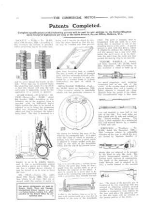
DETACHABLE WHEELS—Pugh.-No. 18,300, dated let September, 1908. --This invention relates to detachable wheels and has particular reference to the means for locking the nave of the wheel to the permanent huh. It is usual with this class of wheel to provide a locking ring that carries a pawl which is adapted to engage ratchet teeth provided on the nave of the detachable wheel, and the aim of the present unveil thin is to provide such a loekinadevice wherein the pawl may easily be disengaged from the ratchet teeth so as to facilitate the removal of the wheel. A pawl is carried by a cover that is secured to the locking ring arid is provided with a projection that extends through a. slot in the locking ring so as to engage with ratchet teeth on a ring that is secured to the nave of the detachable wheel. The pawl is normally held in engagement with the teeth by a wire spring that is mounted on one of the attaching screws of the cover. A special spanner is used with this device, which is adapted to embrace the locking ring, and this spanner has a cam lever that enters the pawl cover so as to disengage the pawl from the teeth and thus permit the locking ring to be removed.
VEHICKE WHEELS.—J. Sankey aLid Sons, Limited,--No. 20,126, dated 25th September, 1908.—According to this invention a wheel is built up of two metal stamp rigs, each stamping constitutes half or one side of the wheel. A flat circular sheet of metal is placed between dies, and a number of radial channels is stamped out; these channels form the spokes of the wheel. The circumferential edge is then spun
over and doubled to form half or one side of the rim. Two such sides are then placed side by side and welded by the electric-welding process. The whole is then mounted on a substantial boss and secured thereto by a number of bolts and nuts.
WRENCHES. — Woodbury. — No. 26,256, dated 4th December, 1908.— This invention relates to adjustable wrenches of the type in which the jaws are carried by separate handles or shanks that are adapted to be grasped by the hand to grip the work. The present improvement consists in the various novel features of construction. The shank of the stationary jaw extends through, and is adapted to ftt into, a recess formed in the movable
jaw. The shank of the movable jaw is constituted by two stampings that are screwed or otherwise suitably secured together. The fnlerum point of the two handles is arranged in close relation tc the jaws and above the adjusting nut. so that the latter will be relieved of the greater portion of the strain.