


A Centrifugally Engaging But Always Freeable Clutch
Page 36
If you've noticed an error in this article please click here to report it so we can fix it.
ACLUICH of the type operated by the engine revolutions forms the subject of patent No. 546,795, from Armstrong Siddeley Motors, Ltd., and F. Holister, both of Park Side, Coventry. Its two main features are that it is free when the engine is stationary or running at low speed and that it can be disengaged manually at any engine speed.
By reference to an accompanying drawing it will be seen that the clutch is of conventional design as regards the withdrawal mechanism, the novelty residing in the flywheel portion.
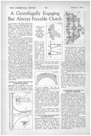
The main flywheel (1) is provided . with a bolted-on stop plate (2), which limits the inward movement of the presser plate (4) through the medium of adjustable setscrews (3), and further acts as an outward stop for the centrifugally moved abutment plate (5).
In action, centrifugal force, acting on pivoted bobs (8), exerts an outward pressure on the plate 5, via stiff springs (7), and forces the plates into engagement. With a fall in speed below the critical value, the abutment plate (5) is retracted bysprings (6) and the clutch becomes free. At any time manual withdrawal of the presser plate (4) may be effected in the usual way, the stop plate (2) then absorbing any centrifugally developed force there may .be.
The object of the centrifugal arrangement is solely to engage the clutch automatically and does not increase the pressure by which the disc is gripped, this being limited by the presserplate springs.
SYSTEM OF WOOD FILLETS FOR COMPOSITE BODIES
PATENT No 546,965 comes from Brush Coachwork, Ltd., and H. Hatton, both of Nottingham Road. Loughborough, 'and discloses a modified
.
detail in the C onstruction of doubledec k bodies. -The patent ' states that in such bodies the roof, floor and panelling are usually screwed directly to the metal framework, and the resulting
rigidity often causes the fixing screws to fail owing to vibration and relative movement.
The suggested improvement lies in the use of a wood intermediary between the rigid girder work and the floors,
roof and panelling. By way of example two specimens of the proposed .method are illustrated.
Vertical pillars (1) form the main uprights of the body, extending right to the cantrails of the upper saloon. Each upright is of U-section, and the inside of the U houses a wood fillet (4) to which the exterior panelling (5) or window frames are attached by wood screws. The wood, being more resilient than metal, does not stress the screws to the same extent ; the specification says that the wood is " kinder' than metal.
The top floor is similarly insulated. Channel girders (2) carry wood inserts (3) to receive the fixing screws of the floor (6).
TUYERE DESIGN FOR EFFICIENT GAS GENERATION IMPROVEMENTS in tuyere design for 1 a gas producer form the subject of patent No. 546,936, from N. Adams and Gas Producers (Bellay), Ltd., Universal House, 60, Buckingham Palace Road, London, S.W.1. The advantages are said to consist of improved cooling coupled with an efficient formation of air blast. Al shown, the tuyere is arranged to slope downwardly into the fire, the angle being approximately 30 degrees. It is a water jacketed structure, formed in welded-steel plates. The air inlet (3) is square at the entrance, but tapers both ways
towards the nozzle, terminatingin a long narrow slot (2). The surrounding water -jacket is divided by baffle plates (1) to ensure complete circulation by avoiding stagnant spots.
The water connections (4) are placed one on each side so that the flow, as well as being longitudinal, is also trans verse. Cooling water enters by the lower hole.
. The proposed main dimensions are given in the specification. For a 26 h.p. engine the nozzle would be 4 ins, by in., the air inlet would be 11 ins, square, and the tuyere would _extend into the combustion space for about 3 ins. For a small car engine the slot would be 2 ins. by 5-32 in., with the other dimensions in proportion.
TYRE-TREAD CAVITIES TO IMPROVE ADHESION ACCORDING to patent No. 546,875, from the Dunlop Rubber Co., Ltd., and others, 1, Albany Street, London, it is known that a tyre having good non-skid properties can be produced by forming the tread with alternate regions of hard and soft rubber. Such a construction, however, leads to considerable complications in manufacture, and a tyre embodying it is much more expensive to make than one produced from a homogeneous mixture.. To obtain equivalent non-skid performance from a tyre of uniform composition is the object of the imProved design described in the specification.
It is proposed to soften alternate portions of the tread by forming groups qf small holes, as shown in the drawing, the local weakening caused thereby having the same effect as a softer grade of rubber. Holes are also formed in the side of the tread where, by their pumping action, they exercise a valuable cooling effect.