


Lorry Has Built-in Loading Jib
Page 58
If you've noticed an error in this article please click here to report it so we can fix it.
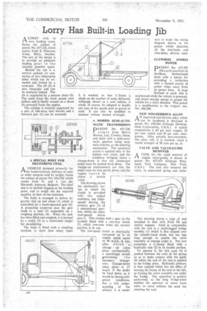
ALORRY with its own loading crane forms -the subject of patent No. 657,326, which comes from S. Peterson, Vinas, Mora, Sweden. The aim of the design is to provide an adequate loading gear in t he smallest possible space.
Behind the cab is a vertical column (1) consisting of two telescoping tubes which can be extended and locked by a cross-pin. The jib (2), is also telescopic and can be similarly locked. The jib is supported by a tension chain (3). The cable from the hook passes over pulleys and is finally wound on a drum (4) powered from the engine.
The column is laterally supported by a pair of side-stays (not shown) and a forward pair (5) can be attached.
A SPECIAL BODY FOR DELIVERING COAL A VEHICLE designed primarily for I—Idle house-to-house delivery of coal, or other material sold by weight, forms the subject of patent No. 656,520, which comes from W. and J. van der Merwede,.Antwerp, Belgium. The chief aim is to abolish bagging at the loading point, and to weigh out the required quantity in view of the customer.
The body is arranged to deliver by gravity into an exit chute (1) which is controlled by a hand-operated gate (2). A projecting extension past the gate leads to a sack (3) suspended on a weighing machine (4). When the sack has been filled and weighed, it is hoisted by a tackle (5) to a convenient height for shouldering.
The hoist is fitted with a counting machine to show how many times
worked, so that it forms .a check on the number of sacks delivered. Although shown as a coat vehicle, it could, of course, be adapted to handle any type of dry goods such as gravel or sand. It can also be modified to measure volume instead of weight.
it is
A MORRIS SEMI-AUTOMATIC TRANSMISSION PATENT No. 657,228, I comes from Morris Motors, Ltd„ Cowley, Oxon, and deals with a semi-automatic gearbox using magnetic clutches as the selecting mechanism. The automatic action is applied only to the highest two ratios, and the condition bringing about a change-down is that the accelerator pedal must be pushed hard down. The change-up requirements are that the pedal must be only partly down, and the engine speed be above a certain value.
The drawing shows the mechanical layout in which the clutch is provided with two output members, one (highspeed) driving the primary gear (2) of a conventional gearbox, whilst the other (low-speed) drives gear 2. This meshes with a gear on the layshaft fitted with a one-way clutch (3), which overruns when the normal gearbox is in use.
The low-speed clutch is electrically energized up to an engine speed equal to 40 m.p.h. in top, after which a change up takes place automatically, a centrifugal switch performing the necessary changeover. Change-down takes place at 37 m.p.h. if the pedal be hard down, as it would be during fullpower conditions. For a full understanding of the scheme, it is nem sary to study the Wiring diagram shown in the patent which describes all the interlocks and time-delay devices used.
FLYWHEEL STORES POWER.
PATENT No. 657,582 (Maschinenfabrik
Oerlikon, Switzerland) deals with a means for providing a "trolleybus with a limited source of power when away from its power lines. A large flywheel is used; this is accelerated while the vehicle is powered, and stores enough energy to propel the vehicle for a short distance. This patent is a modification to the original one, No. 600,280.
NEW NON-FERROUS ALLOY
AN improved non-ferrous alioy which can he hardened is disclosed in patent No. 658,264 (Chicago Development Corporation, U.S.A.). A typical composition is 60 per cent. copper, 20 per cent. nickel and 20 per cent. manganese. After suitable heat-treatment, this alloy will, it is claimed, reach a tensile strength of 90 tons per sq. in.
VALVE AND VALVE-GUIDE REMOVER
ATOOL for the rapid removal of engine valve-guides is shown in patent No. 657,453 (Chicago Pneumatic Tool Company, New York, U.S.A.). The tool also removes the valve, its associated spring and collar.
The drawing shows a type of tool intended to deal with Ford V8 and similar engines. Used in conjunction with the tool is a multi-legged bridge member (I) which is first slipped over the cylinder-head studs; this has legs long enough to enable the valve assembly to emerge under it. The tool comprises a C-clamp fitted with a hydraulic ram (2) in its handle portion.
To operate it, the thin nose (3) is pushed between the coils of the spring so as to make contact with the guide .(4) whilst the end of the ram is applied to the bridge piece. Hydraulic pressure is then applied which has the effect of moving the frame of the tool to the left, so forcing the valve assembly out under the bridge. The operation is quickly performed, as the long bridge-piece enables the operator to move from valve to valve without the need for resetting the tool.