


Albion's Latest Oil Engine
Page 60
Page 61
If you've noticed an error in this article please click here to report it so we can fix it.
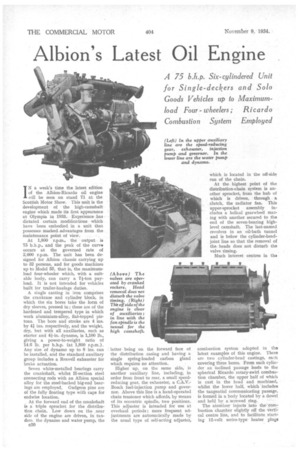
IN a week's time the latest edition of the Albion-Ricardo oil engine will be seen on stand 71 at the Scottish Motor Show. This unit is the development of the high-camshaft engine which made its first appearance at Olympia in 1933. Experience has dictated certain. modifications which have been embodied in a unit that possesses • marked advantages from the maintenance point of view.
At 1,800 r.p.m., the output is 75 b.h.p., and the peak of the curvar occurs at the governed rate of 2,000 r.p.m. The unit has been designed for Albion chassis carrying up to 32 persons, and for goods machines up to Model 55, that is, the maximumload four-wheeler which, with a suitable body, can carry a 7i-ton payload. It is not intended for vehicles built for trailer-haulage duties.
A single casting in iron comprises the crankcase and cylinder block, in which the six bores take the form of dry sleeves, pressed in ; these are of the hardened and tempered type in which work aluminium-alloy, flat-topped pistons. The bore and stroke are 4 ins. by 4i ins, respectively, and the weight, dry, but with all auxiliaries, such as starter and 4i-in. dynamo, is 1,100 lb., giving a power-to-weight ratio of 14.8 lb. per b.h.p. (at 1,800 r.p.m.). Any size of dynamo up to 8 ins, can be installed, and the standard auxiliary group includes a Reavell exhauster for brake actuation.
Seven white-metalled bearings carry the crankshaft, whilst H-section steel connecting rods with an Albion special alloy for the steel-backed big-end bearings are employed. Gudgeon pins are of the fully floating type with caps for endwise location.
, At the forward end of the crankshaft is a triple sprocket for the distribution chain. Low down on the near side of the engine are driven, in tandem. the dynamo and water pump, the c30 latter being on the forward face of the distribution .casing and having a single spring-loaded carbon gland which requires no attention.
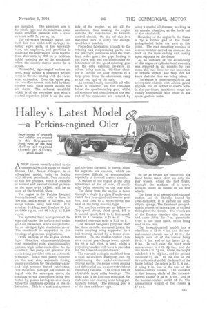
Higher up, on the same side, is another auxiliary line, including, in order from front to rear, a small speedreducing gear, the exhauster, a C.A.V.Bosch fuel-injection pump and governor. Above this line is a hand-operated chain tensioner which affords, by means of its eccentric spindle, two positions. This adjuster is intended for use at overhaul periods; more frequent adjustments are automatically made by the usual type of self-acting adjuster,
combustion system adopted in the latest examples of this engine. There are. two cylinder-head castings, each covering three bores. From each cylinder an inclined passage leads to the spherical Ricardo rotary-swirl combustion chamber, the upper half of which is cast in the head and machined, whilst the lower half, which' includes the tangential communicating passage. is formed in a body located by a dowel and held by a screwed ring.
The atornizer injects into the corn bustion chamber slightly off the vertical centre line, and to facilitate starting 12-volt series-type • heater plugs are installed. The atomizers are of • the pintie type and the maximum brake mean effective pressure with a clear exhaust is 90 lb. per sq. in.
The valves are vertically placed, and each has two collet-held springs; inserted valve seats, of the renewable type, are employed, and provision is made for the inlet valves to be lowered from their seats by .003 in, to facilitate initial speeding up of the crankshaft when the electric starter motor is in action.
Plain-ended, right-angled rockers are used, each having a clearance adjustment in the end mating with the valvestem extremity. Over the valve gear are two alloy covers, each held by three captive nuts; these covers include the air ducts. The exhaust manifold, which is of the two-piece type with a central expansion joint, is on the near
side of the engine, as are all the auxiliaries, thus making the engine suitable for installation in forwardcontrol chassis. On the off side is a machined face to carry the changespeed-lever bracket.
force-feed lubrication attends to the rotating and reciprocating parts, and the gear-type pump also feeds the overhead valve gear ; the pipe leading to the valve gear and the connections for lubrication of the speed-reducing gear are the only external oil-ways, all others being cast in. Oil-filter cleaning is carried out after removal of a large plate from the aluminium sump at the rear end of the unit.
An external easily accessible oil-relief valve is mounted on the crankcase below the speed-reducing gear, whilst oil economy and cleanliness of the rear end of the crankcase' are ensured by
using a special oil thrower, working in an annular chamber, at the back end of the crankshaft.
Mounting of the engine in the frame is by a rubber pad at the front; spring-loaded bolts are used at this point. The rear mounting consists of a cross-member carried on studs at the back of the main casting and resting upon supports on the frame.
As an instance of the accessibility of this engine, a cylinder-head assembly was removed in six minutes by two men; this was done for our inspection of internal details and they did not know that the time was being taken.
The engine is interchangeable in the appropriate chassis with Albion petrol
• engines, and its output at speeds within the previóuslvl mentioned range are closely comparable with those of the spark-ignition units. •