


NEW THORNYCRO FT PRODUCT,
Page 56
Page 57
Page 58
If you've noticed an error in this article please click here to report it so we can fix it.
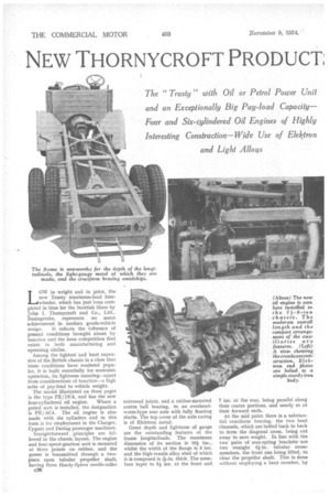
-a 7-3. 8-Ion Chassis and an Oil Engine LOW in weight and in price, the new Trusty maximum-load fourwheeler, which has just been completed in time for the Scottish Show by John I. Thornycroft and Co., Ltd., Basingstoke, represents no mean achievement in modern goods-vehicle
design. It reflects the influence of present conditions brought about by taxation and the keen competition that exists in both manufacturing and operating circles.
Among the lightest and least expensive of the British chassis in a class that these conditions have rendered popular, it is built essentially for economic operation, its lightness ensuring—apart from considerations of taxation—a high ratio of pay-load to vehicle weight.
The model illustrated on these pages is the type PE/DC4, and has the new
four-cylindered oil engine. Where a petrol unit is installed, the designation is PE/ AC4. The oil engine is also made with six cylinders and in this form is for employment in the Charger, Cygnet and Daring passenger machines.
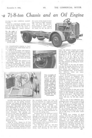
Straightforward principles arc followed in the chassis layout. The engine and four-speed-gearbox unit is mounted at three points on rubber, and the power is transmitted through a twopiece open tubular propeller shaft, having three Hardy-Spicer needle-roller c26 universal joints, and a rubber-mounted centre, ball bearing, to an overheadworm-type rear axle with fully floating shafts. The top cover of the axle casing is of Elektron metal.
Great depth and lightness of gauge are the outstanding features of the frame longitudinals. The maximum dimension of its section is 10i ins., whilst the width of the flange is 3 ins. and the high-tensile alloy steel of which
it is composed is thick. The members taper to 5+ ins, at the front and
7 ins, at the rear, being parallel along their centre portions, and nearly so at their forward ends.
At the mid point there is a substantial cruciform bracing, the two bent channels, which are bolted back to back to form the diagonal cross, being cut away to save weight. In line with the two pairs of rear-spring brackets are two straight 3i-in. tubular crossmembers, the front one being lifted, to clear the propeller shaft. This is done without employing a bent member, by
type channel-section member is fixed with screws to the closed front ends of the longitudinals.
In front of the engine, and supporting the central mounting, is a straight box-type member, its attachment being supplemented by plates bolted to the main members. The cab-floor brackets, incidentally, are fixed where the frame is thus reinforced.
Where the engine feet, bolted to the bell-housing, rest on their bearers within the longitudinals, each channel is stiffened by two obliquely disposed plates, placed one on each side of the bearer, Specially noteworthy for their slender appearance are the spring brackets, shackles, and indeed the springs themselves. Scientific design and the use of high-quality alloy-steel, have 'enabled their dimensions to be kept so small. Each rear spring is made up of only five leaves. They are, however, of unusual thickness. The springs are secured to the axles by diagonal bolts in the usual Thornycroft manner.
The front axle and steering heads also follow customary Thornycroft practice, but the steering box is a Marles product.
Shoes in 17-in, drums on all four wheels are expanded by either the hand lever or the pedal, the latter operating through a Dewandre vacuum cylinder. A common cross-shaft is carried below
the cross-shaft, whilst that from the lever is attached to a rigid arm inside the frame by a yoke, slotted to permit independent forward motion. A double-ended arm on each side operates the four front and rear-wheel brake lines. A hook-up link is provided in each to allow articulation in line with the spring ends.
Incorporated in the bulkhead behind the Power unit is an air passage through which the warm currents from the bonnet are dispersed. This is simply effected by panelling the bulkhead frame on both sides. Rigidity is a characteristic of the whole of this structure, including the wings.
The PE/AC4 and the PE/DC4 chassis weigh 31 and si tons respectively, thus allowing 15 cwt. for a
body: the unladen weights are 4 tons and 41 tons, The former sells at £750 and the latter £900. In both cases the wheelbase is 12 ft. 8 ins:, the body space 18 ft, 4 ins., and the frameheight 2 ft. 11 ins,; 36-in. by 8-in. tyres are used, with twins on the rear wheels, Correct weight distribution has been obtained by setting the frontaxle well back.
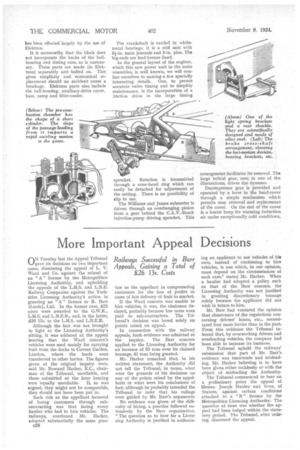
With regard to the new oil engine, this may be broadly described as incorporating the best features of the ACtype petrol and CID-type compression-ignition units. In its construction, however, there are many noteworthy points.
As on its oil prototype, a pre-combustion chamber is employed, this being in shape a short cylinder on a horizontal transverse axis. Fuel is injected, at a pressure of 1,400 lb. per sq. in., vertically downwards into it, through a single-hole injector, whilst a passage, directed to impart a swirling motion to the gases, connects the cell with the cylinder.
One improvement in this part of the design is a modification in the sectional shape of this passage to give highe4 velocity to the gases. The compression ratio is 17 to 1, and the bore and stroke 105 mm. by 152 mm. respectively.
In the case of the 5.255-litre fourcylindered unit, which is rated at 27.23 h.p., 65 b.h.p. is developed at 2,200 r.p.m.—the governed speed—whilst the maximum torque, at 1,200 r.p.m., is 182 lb. ft. A consumption rate of 0.45 lb. per b.h.p.-hr. has been obtained. The DC6 unit (7.88 litres) has an output of 105 b.h.p. at the same crankshaft speed.
A simple iron casting, of great solidity, with flat top, base and ends, constitutes the main body of the engine. In it are accommodated lightly pressed-in wet liners with rubberjointed lower seatings, whilst the main bearings are well above its lower face. Rigidity has obviously been the designer's first aim. Elsewhere, but not here, weight saving is apparent, and it has been effected largely by the use of Elektron.
It is noteworthy that the block does not incorporate the backs of the bellhousing and timing case, as is customary. These parts are made (in Elektron) separately and bolted on. This gives simplicity and economical replacement should an accident cause a breakage. Elektron parts also include the bell-housing, auxiliary-drive cover, base, sump and filter-cooler. The crankshaft is carried irt• white. metal bearings; it is a stiff unit with 3i-in. main journals and 3-in. pins. The big-ends are lead-bronze lined.
As the general layout of the engines, which this new power unit in the main resembles, is well known, we will confine ourselves to naming a few specially interesting details. One, to permit accurate valve timing and to simplify maintenance, is the incorporation of a friction drive in the large timing sprocket. Rotation is transmitted through a cone-faced ring which can easily be detached for adjustment of the setting. There is no possibility of slip in use.
The Williams and James exhauster is driven through an overhanging pinion from a gear behind the C.A.V.-Bosch injection-pump driving sprocket. This arrangement facilitates its removal. The large helical gear, seen in one of the illustrations, drives the dynamo.
Decornpressor gear is provided and operated by a lever in the head-cover through a simple mechanism which permits easy removal and replacement of the cover. On the end of the cover is a heater lamp for warming induction air under exceptionally cold conditions.