


A Résumé of Recently Published Patent Specifications
Page 54
If you've noticed an error in this article please click here to report it so we can fix it.
A Four-wheeled Axle Assembly
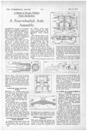
A MERICAN practice in six-wheeler .1-1 design is exemplified in patent No. 584,930, which comes from Willys-Overland Motors Incorporated, Toledo, Ohio, U.S.A. This patent gives particulars of a twin-axle driving assembly, in which the suspension arrangements form the chief point of interest. Conventional leaf springs are employed, used in pairs, one above and one below a central tubular crossmember (1). Each spring is free to rock about a trunnion pin (2) carried by a bracket. The spring ends are pivotally attached to axle-casing plates (3), but although the front plate is welded to the axle tube, the rear one (4) is pivotally mounted. The axles are controlled in their movements by torque rods (5), which maintain the position with respect to the frame. The axle-to-axle position is governed by another rod (6) located
between them. The aim is to ensure that, at all times, the road-wheels will
remain par frame. To define the maximum drop of the axles from the frame, spring-loaded limitlinks (7) are provided at both ends. These ensure that the universal joints in the drive cannot be stressed by excessive deflection.
INJECTOR WITH TWO FUEL PATHS
DATENT No. 584,060 comes from Joseph Lucas, Ltd., and F. Marlow, both of Great King Street, Birmingham, 19, and discloses a novel design for a fuel injector. There are two separate fuel systems in it —one for idling and the other for the load range. The drawing shows a longitudinal section and an end-on section on the line A-A. Two fuel ducts (1 and 2) eachlead to a separate pair of curved grooves cut in a conical swirl-plug (3). The idling fuel .emerges from a pair of diametrically opposed small orifices (4), whilst the full-load charge is ejected fromlarger bores (5). No details are given of the special injection pump. CONTROLLED EXPANSION FOR ALLOY PISTONS A LIGHT-ALLOY piston, fitted with .C1. restraining rings to govern the expansion, forms the subject of patent No. 584,336, which comes from L Howlett and Wellworthy Piston Rings, Ltd., 89, Blackfriars Road, London, S.E.1. The drawing shows a section of the proposed piston, which is of the type employing a T-shaped slit in the skirt to accommodate the high expansion of the alloy. In addition to the normal ringgrooves, two more are pro vided, as may be seen at land 2. Each of these grooves contains an unsplit ring made of material similar to w that of the cylinder walls. These rings, which are assembled by being initially split and then welded up in place, are a close fit in their grooves and are claimed to limit the expansion of the piston
After several thousand vehicle-miles, the pistons may be subjected to a rolling operation on the face (3), a treatment said to allow greater expansion. BOGIE-AXLED SUSPENSION SYSTEM
T?enable driving and braking reacions to be better handled by a leaf spring is the object of modifications shown in patent No. 585,144, by P.
Cowell and Kirkstall Forge, Ltd., both of Kirkstall Forge, Leeds, 5. In this scheme, the major leaf, which would normally be the longest, is shorter than its neighbour, and is pivoted at its ends to flat plates, which make contact with the next leaf.
Referring to the drawing, the lowest leaf is pivoted at point I to a female socket (2), which surrounds a hollow ball (3) carried on the shackle pin. The second leaf lies on top of the socket member and is turned over, as shown_ at 4, to embrace a pin, which has the effect of maintaining ths..., assembly under rebound conditions.
In operation, most of the braking and driving reactions would be taken by the bottom leaf, whilst the vertical load would be handled in the normal Manner by the whole spring.
AN AMERICAN EARTH-WORKING MACHINE
THE useof powerful machines for shifting earth in bulk is becoming of increasing interest, and No. 584, patent N697 shows an American type called a push-grader. The patentee is a specialist concern, R. G. Letourneau Incorporated, Peoria, Illinois, U.S.A. The power unit is a two-wheeled tractor (1) which has to be supported by a trailer (2). The latter is called a carry-type scraper, and consists of a scoop-shaped member (3) which can be. adjusted for working height by means of a cable and drum. . The two units are articulated in a horizontal plane, but are rigid in a vertical sense. One of the pivots is shown at point 4. On the front of the machine is a levelling blade (5), which is also height-controlled by a cable and drum, and it is this unit that performs the function of levelling-off the ground.