


A Continuous-pressure Injection System A Resume of Patent Specifications That
Page 36
If you've noticed an error in this article please click here to report it so we can fix it.
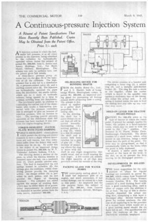
Have Recently Been Published. Copies May be Obtained from the Patent Office, Price 11each AN injection system in which the fuel, under full pressure, is at all times present in the injectors, being admitted, to the cylinders by hydraulically operated valves, forms the subject of patent No. 566,693, from G. Amery and Amery Holdings, Ltd„ Tat Bank House-, Oldbury, Birmingham. The scheme can only be outlined here, Out the patent gives lull details. ,
A three-throw pressure pump (1) forces fuel via the pipe (2) to the injectors of all the cylinders. The highpressure line is also led to a distributor (3), a pressure-control valve (4), and a starting control valve (5). The injectors are hydraulically operated via pipes from the distributor, the needle valves, which are in a state of hydraulic balance, being opened. by a drop in pressure arriving from the distributor.
The accelerator pedal, in addition to controlling the central rod of the distributor, also works a link-motion connected with the pressure controller; this is arranged to give an increase of injection pressure, with an increase in load. The starting control prevents operation of the distributor until full pressure has been reached; it also contains the engine-stopping devie.
TORQUE-RESILIENT CLUTCH. PLATE WITH FLUID DAMPING
i—oRQUE-RESILIENT clutch-plates 1 which permit the driving and driven elements to have a slight relative movement are well known, but they sometimes suffer from the defect that oscillations may be set up. To avoid this is the object of an improved design shown in patent No. 566,626, by W. V. Thelander, Auburn, Indiana, U.S.A.
The drawing shows a section of the plate, in which the friction member is mounted upon the hub, via a sandwich joint (1), which permits relative rotation. The load is transmitted via coil springs housed in cylinders (2); _the springs give the resilience, whilst closefitting pistons provide the damping action. An escape orifice (3) is provided in each piston, and its size governs the degree of damping obtained. The cylinders are sealed against the escape of working fluid, which may be either thick oil or grease. Other improvements in clutch-plates • are disclosed in another patent from the same source, numbered 566,650, OIL-SEALING DEVICE FOR RUNNING SHAFTS
FROM the Austin Motor Co., Ltd., and J, C. Haefeli, both of Long. bridge Works, Birmingham, comes, in patent No 566,682, an improved sealing gland for preventing oil leakage around shafts projecting from a casing. The scherpe is described as applied to a pulley shaft projecting from a timing case.
In the drawing, the shaft has a screw-thread (1) so cut that oil will be Carried inwardly. Surrounding 1 h e screwed portion i a ring (2), which is a free fit around the shaft and is loosely held from rotation by a pair of pins (3) This freedom of mount. big allows the ring to move with the shaft in any slight irreg-ularities that might occur, and -so avoid wearing the bore larger. A felt washer (4) absorbs the slight quantity of oil that may percolate around the outside of the ring.
PACKING GLAND FOR WATER PUMPS
THE water-pump sealing gland is a small but important part of an engine,and much annoyance, if riot' actual damage, can be caused by a leak at this point. An improved seal for this purpose forms the subject of patent No. 566,441, from General Motors Corporation, Detroit, Michigan, U.S A. The de-Vice consists of a bonded unit comprising a brass ring (1), a rubber ring (2), and a metallic anti-friction "washer (3). The ring fits into a recess in the impeller, whilst the washer (which is keyed to the spindle) runs against.a stationary face on the casing; . this forms the actual seal. A coil spring is housed inside the unit to load the sealing face and take up any wear that may occur. '
HOLD-ON LEVER FOR TRACTOR BRAKE-PEDALS
PATENT No. 566,579 refers to tbe type of tractor in which the clutch pedal, if pressed far enough, applies the brake; the subject is a hand-operated catch, which may be used to hold the
pedal in the " on " position. 'I he inventor is II. Fearn, Pebley Farm, Barlborough, Chesterfield, The device consists of a small lever, which, when moved in one direction, brings a small detent into the path of the pedal. The lever may be spring-biased, so that it automatically holds on the brake when the pedal is fully depressed.
If desired, a safety catch may be inserted at the back of the lever, in the slot, so as to prevent the levet moving to its disengaged position.
DEVELOPMENTS IN BIG-END ALLOYS
THE latest suggestions for the corn. position of alloys for big-end bearings are contained in patent No. 566,360, which comes from Vandervell Products, Ltd., and D. Green, Western Avenue, London, Ny.3. The bearini consists of a steel backing faced with first, a good conducting alloy, such a, silver or copper with the addition o' tin or lead-. On top of this is electrolytically deposited the actual run fling face, comprising a thin layer o tin-copper alloy Several formulx an given for variOus mixtures, the chie aim of all appearing to be the provision of a second -layer which would act a: a good bearing metal should the tor layer fail in use. The specification alsc gives the make-up of the variow electrolytic solutions employed.