


Master Cylinder-cum-servo Braking Unit
Page 35
If you've noticed an error in this article please click here to report it so we can fix it.
N our issue dated November 24 last we dealt with a two-stage hydraulic
iaster cylinder for use in connection
-ith a vehicle braking system, the iventor being Mr. L. Radford, 25-,
hantry Avenue,"Kempston, Bedford.
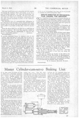
Radford has now submitted to us aother of his ideas .which possesses the 'me merit of simplicity combined with ractica biLity. The objeet of the present invention to add a form of mechanical assistace to the existing braking system, id the manner in which the inventor ro.poses to carry this out is clea~ly lowu in the accompanying drawing. s will be seen the normal vacuum irvo cylinder is piped up to the master. /Ender so that it . can be used as a ioster fur hydraulic brakes or as a rvtir.device for a mechanically operated 'stem.
In the latter case the master cylinder ould be provided with leather cups or ist-iron pistons and rings, the medium ied being a low-viscosity engine oil. should be pointed out that, as shown the drawing, the device is for use ith normal hydraulic-brake fluid.
Reference to this diagram will show
at the high-pressure and low-pressure -tinders. are 'interconnected by means a longitudinal bore formed in the gh-pressure-plunger rod and a spring.
loaded ball valve. This ball valve normally rests on its sealing and thus seals the bore, but when in the position shown the annular flange formed on the end of the low-pressure cylinder forces the ball off its seating.
In operation both plungers advance as one until a predetermined pressure is reached, and this is governed by the degree of tension on the spring. When this tension is overcome the low-pressure' plimger is retarded in relation to the high-pressure plunger, the ball passes away from the annular flange and the bore in the high-pressure plunger rod is sealed, Communication
between the two cylinders being now cut off, the higb-pressure plunger proceeds to increment the pressure already applied to the upper cylinder, which, as shown, operates a lever suitably linked up to the main brake-cross-shaft.
Mr. Radford points out the following 'features of his invention: (1) There is no lost motion, because of the practically instantaneous transfer front low to high-pressure; (2) there i5 a definite two-stage action on the highpressure plunger—there is no pressure behind it—which cancels out wasted energy spent in compressing the tension spring; (3) the accessible and rapid means for altering the pressure at which the change-over occurs resulting in the driver being able to " feel " the degree of application; (4) low initial, cost and the elimination of elaborate systems for utilizing atmospheric pressure.
Communications relative to this 'invention, for which patents are pending, should be sent direct to Mr. Radford at the address given.