


Modern Suspension Systems in Theory and Practice
Page 30
Page 31
If you've noticed an error in this article please click here to report it so we can fix it.
By J. Pickles
IN the preceding article, the salient features of suspension design were discussed, and now it is proposed to show how these principles apply to the Main systems of suspension which Will be available to commercial-vehicle designers in the years following the close of hostilities.
The orthodox beam axle is advan tageous in that it is of simple conception with the minimum of moving parts. Owing to the wide spread which may be obtained at the rear, reslitance to rolling is fairly good, although at the front the narrow spring base is somewhat disadvantageons. This fault, however, is largely offset by the torsional stiffness of the springs, A•feature of the design, which is not found in the newer systems, is that the riding comfort is not affected by widening the spring base to obtain roll stiffness.
This point May, perhaps, be better illustrated by imagin. lug a vehicle with springs mounted immediately over the wheels, Lifting one wheel will result in a deflection of that spring only, and the roll resistance will be very good. If the springs be closed right in to the centre, then both springs will be deflected an equal amount, the total resistance being equal to that of the one situated over
• the wheel.
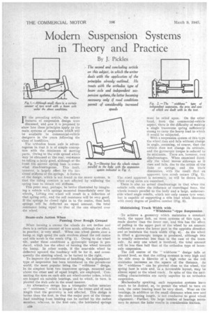
Beam-axle Action When Passing Over Rough Ground
When turning a corner the wheels do not incline and there is a certain amount of tyre scrub, although the effect, in practice, is very small. When one wheel passes over a bump at high speed the axle revolves about the roll centre and side scrub is the result (Fig. I). Owing to the wheel tilt, under these conditions a gyroscopic torque is produced, which has the effect of turning the wheel towards the bump. In other . words, if the near-side wheel be deflected upward the tendency will be for it, and consequently the steering wheel, to be turned to the right.
To improve the conditions of handling, the independent type of suspension has been introduced in the private-car world, the most popular being the " wi4hbone design. In its simplest form two transverse springs, mounted one
• above the other and of equal length, are employed. Connecting the eyes on each side are wheel-carrier yokes, which are binged on suitable bearings, and to which, in turn, is pivoted the stub axle in the usual manner.
An alternative design has a triangular radius member or " wishbone," which is hinged to the frame and of such length that the geometry is not affected, This design is better than the first, in that the major part of the thrustload resulting from braking Can be carried by the radius member, whereas, in the first case, the laminated springs must be relied upon. On the other hand, from the commercial-vehicle aspect, there is the difficulty of making a single transverse spring sufficiently strong to carry the heavy load to which it would be subjected.
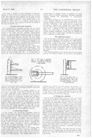
With a suspension system of this type the wheel rises and falls without change in angle, assuming, of course, that the vehicle does not change its attitude, and the gyroscopic torque is• reduced to its minimum. There are, however, two disadvantages. When eXamined frontally the wheel moves sideways as it rises and falls, due to the action of the links or springs, and the traek diminishes, with the result that an . apparent tyre .scrub occurs (Fig-. 2). The word apparent is necessary, as will be Shown later, when swing axles are examined.
There is also an actual disadvantage in that when • the vehicle rolls under the influence of centrifugal force, the wheels remain parallel to the body and a 'large, unfavourable wheel angle reiults, which not only causes tyre wear, but is capable of supporting a side load which decreases • with every degree of positive camber (Fig. 3).
Maintaining Track Width with
"Wishbone"-type Suspension
-To achieve a. geometry which maintains a constant track, the upper link, on most systems of this type, is made shorter than the lower one, and this has the effect of pulling in the upper part of the wheel by an amount sufficient to move the lower part in the opposite direction and so 'maintain the track width (Fig. 4). As the wheel is tilted a gyroscopic torque is produced, although this is usually somewhat less than in the case of the beans axle_ As only one wheel is involved, the total amount will be less than half that of the orthodox type of beamaxle suspension.
The roll centre of the " wishbone " design -falls at ground level, so that the rolling moment is very high and the side sway is likewise of a high order as the roll resistance increases as the square of the distance. As the " wishbone " can be pivoted close to the wheel, the spring base is wide and, in a favourable layout, may be almost equal to the wheel track. In spite of this the antirolling characteristics are rarely superior to an orthodox suspension.
Mechanically speaking, such suspension systems leave much to be desired, as, to permit the wheel to turn on lock, the outer bearing must be very short. Wear on the bearings, in addition to the small clearance when new and the short bearing length, is not conducive to good wheel alignment. Further, the large number of bearings necessary to mount the links results in considerable friction. . The result is similar to that occurring in' laminated springs, in that the frictional. resistance must be overcome before the wheel can niove relative to the body, so that some shock must be transmitted to the occupants before the spring deflects resiliently. With torsion• bars or coil springs, in which there is no friction, shock absorbers provide the whole pf the damping, which may be applied at the most favourable time.
Parallel-action-type Systems . True parallel-action springing systems are of several types, although they are not so widely used in this country as on the Continent. In the most simple design a lever is pivoted to the frame, and lies, normally, approximately horizontal. The road wheel is mounted at the rearward end so that, considered frontally, it rises and falls on a straight plane Viewed from the Side, however, the lever swings about a fixed centre so that the king-pin axis 'will change with the wheel angle, and the caStor will consequently' not be'constant. To minimize this failing the length of the lever 'must be made as long as possible, with the limitation set by the length of the frame forward of the axle.
A development of tbiS principle has been widely used by Dr. Porsche, and is a feature of the Volkswagen Two arms are used to support each wheel,being mounted one above the othet to give a parallelogram linkage, thus main taining the castor angle (Fig. 5). It is enstomary to mount the arms hi bearings carried on transverse tubes, which also function a.s robust front cross-members, not only stiffening the frame, but presenting excellent protection against damage bycollision.'
At one end torsion bars are usually coupled to the levers and at the other to the tube in which it is housed, the whole suspension being completed by the shock absorbers which are carried in the end of the_tubes to provide a layout of exceptional neatnesS and economy. There is, however, a disadvantage in that the arm., being of cantilever form, must be robust, not only to resist cornering loads, but to withstand kerb impacts, a contingency which would require to be particularly guarded against on passenger-service vehicles. This type of suspension has fine riding qualities, in that the forward mounting of the springs gives a spring base longer than that of the wheelbase, so that pitching is reduced.
A Coil-spring 'Design In this country, the Armstrong suspension, which is based on the Porsche design, is interesting in that a coil spring is utilized for the resilient member and is mounted in an ingenious manner. Theupper lever is of bell-crank, farm with the second leg pendant. The lower lever is also of the bell-crank type and the second arm is upright, forming, with the other pendant portion, reaction and force points without recourse to what its, sometimes, a difficult form of, frame .mounting. The whole suspension. unit can be assembled to the frame as a unit.
Also of the parallel-action class' is the sliding pillar or sleeve type (Fig 6), which comprises, essentially, a, normal axle bolted to the frame, but with an extended king-pin permitting the stub axle to slide up and down upon it against a helical spring. This design suffets from the disaa.antage§ of sliding friction as. opposed to rotary frietion, and it is difficult to provide a reasonable deflection without. making the proportions of unreasonable magnitude.
Suspension systems ofthe parallel-action type suffer from a common difficulty, in that the accuracy of the steering linkage is not easily made possible at all wheel positions. Obviously, if the wheel rises in a straight line the distance between the steering arm ends tends to increase, and as this is prohibited by the track rod, toe-out roust occur. Except. in the case of the sliding-sleeve design, for which there is no method of attaining an accurate linkage, satisfactory results may be obtained by using a drag link to each wheel, although the expense is rarely considered to justify itself.
The Dubonnet Layout
One' of the most satisfactory layouts from every point of view is the Oubonnet, which is based on a single tubular cross-member, resembling a, normal axle in that king-pin bearings.are rarried at the ends. Large fabricated arms pivot in the bearings and lie, rearward. Pivoted to these members; at the rear, and lying forward, are further arms in which the wheel is mounted. Coil or torsion springs are carried in the fabricated arm', as are the shock 'absorbers.
The springing system is thus all-steered, and the steering arms do not move in respect to the frame, permitting a
steering layout which is at once strnp:e and accurate. A further invaluable feature is that the torque reaction, imposed by the brake back plate on the spring arm, tends to lift up its pivoted end and, consequently, the front end of the frame, thus counteracting the tendency of the vehicle to swing forward When stopping.
A Change.not Justified In. view of the imperfections which are still to be found in the several 'systems of independent suspension. what advantages, one may ask,_ will be gained by the use of such systems on commercial vehicles? There is some small benefit in that the absence of a front axle beam will permit a considerable reduction of the engine height and, consequently, a lower transmission line, but beyond this there is little to be said in faltour of any departure from the orthodox suspension so long as the law remains unaltered. The handling of a commercial vehicle is certainly not affected in any measurable degree by cornering at present speeds, nor is gyroscopic torque reaction at all noticeable. Should the-roads in the post-war years be built to the standards required by modern traffic, and should understanding dawn on those that frame our laws that lives are not lost as a result of a designer's inability to produce safe vehicles, nor drivers to handle them, then speeds may become' perthissible which will render the employment–of intlependent suspension necessary.' especially for longdistance passenger vehicles.
It:is to be hoped, however, that they will not be introduced merely as a selling point,:as has been done on some private cars, where' the conditions 'do not seem to warrant suchdevices.