Sleeve Valve for Better Scavenging
Page 40

If you've noticed an error in this article please click here to report it so we can fix it.
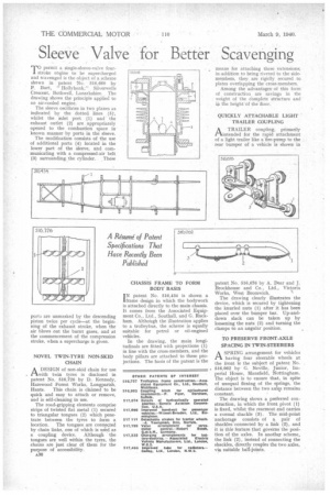
permit a single-sleeve-valve four stroke engine to be supercharged and scavenged is the object of a scheme shown in patent No. 516,668 by P. Burt, " Hollybank," Siiverwells Crescent, Bothwell, Lanarkshire. The drawing shows the principle applied to an air-cooled engine.
The sleeve oscillates in two planes as indicated by the dotted lines (5), whilst the inlet port (I) and the exhaust outlet (2) are appropriately opened to the combustion space in known manner by ports in the sleeve.
The modification consists of the use of additional ports (4) located in the lower part of the sleeve, and communicating with a compressed-air belt (3) surrounding the cylinder. These ports are unmasked by the descending piston twice per cycle—at the beginning of the exhaust stroke, when the air blows out the burnt gases, and at the commencement of the compression stroke, when a supercharge is given.
NOVEL TWIN-TYRE NON-SKID CHAIN
ADESIGN of non-skid chain for use with twin tyres is disclosed in patent No. 516,726 by D. Kennedy, Harewood Forest Works, Longparish, Hants. This chain is claimed to be quick and easy to attach or remove, and is self-cleaning in use.
The road-gripping elements comprise strips of twisted fiat metal (1) secured to triangular tongues (2) which penetrate between the tyres to form a location. The tongues are connected by chain links, one of which is used as a coupling device. Although the tongues are well within the tyres, the chains are just clear of them for the purpose of accessibility.
A30 CHASSIS FRAME TO FORM BODY BASIS IN patent No. 516,434 is shown a frame design in which the bodywork is attached directly to the main chassis. It comes from the Associated Equipment Co., Ltd., Southall, and G. Rackham. Although the illustration applies to a trolleybus, the scheme is equally suitable for petrol or oibengined vehicles.
In the drawing, the main longitudinals are fitted with projections (1) in line with the cross-members, and the body pillars are attached to these projections. The basis of the patent is the means for attaching these extensions; in addition to being riveted to the sidemembers, they are rigidly secured to plates overlapping the cross-members.
Among the advantages of this form of construction are savings in the weight of the complete structure and us the height of the floor.
QUICKLY ATTACHABLE LIGHT TRAILER COUPLING
A TRAILER coupling, primarily rtintended for the rapid attachment of a light trailer like a fire-pump to the rear bumper of a vehicle is shown in
patent No. 516,676 by A. Dear and J. Brockhonse and Co., Ltd., Victoria Works, West Bromwich.
The drawing clearly illustrates the device, which is secured by tightening the knurled nuts (I) after it has been placed over the bumper bar. Up-anddown slack can be taken up by loosening the nuts (2) and turning the clamps to an angular position.
TO PRESERVE FRONT-AXLE SPACING IN TWIN-STEERERS
ASPRING arrangement for vehicles having four steerable wheels at the front is the subject of patent No.
• 516,062 by G. Neville, Junior, Imperial House, Mansfield, Nottingham. The object is to ensure that, in spite of unequal flexing of the springs, the distance between the two axles remains constant.
The drawing shows a preferred con. struction, in which the front pivot (1) is fixed, whilst the rearmost end carries a rormal shackle (3). The mid-point anchorage consists of a pair of shackles connected by a link (2), and it is this feature that governs the position of the axles. In another scheme, the link (2), instead of connecting the shackles, directly couples the two axles, via suitable ball-joints.


