Uniform Damper Setting
Page 50

If you've noticed an error in this article please click here to report it so we can fix it.
I T has been generally agreed that the reduction or .elimination of friction between the leaves of a road spring is desirable if the free oscillations are to be effectively damped. Whilst a certain amount of leaf friction continues to .be a design factor in heavy-vehicle suspension systems, the shock absorber is looked upon as essential equipment on all types of chassis intended for reasonably high operating speeds.
Overseas operators, in particular, consider the shock absorber indispensable and demand a high standard of performance and reliability under the most exacting conditions.
The ability of the maker to supply dampers which operate within close tolerances of a predetermined resistance is obviously a pre-requisite to planned suspension performance, but because of the parasitic-leakage bugbear, accurate setting On a production line presents a difficult problem.
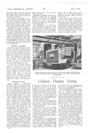
A flow rig which not only reduces the setting tolerances to a ,negligible figure, but which virtually eliminates any chance of a faulty setting being made, has been designed and built by Girling, Tyseley, Birmingham. The dampers concerned are of the telescopic type, and the flow rig is equipped with two stations for setting the rebound and bump valves independently.
The essential features of each station are: (1) a means for setting the valve with the operative damper parts mounted in the fixture so that the resistance to fluid flow through the damper equals a prescribed figure irrespective of the amount of parasitic leakage; (2) high and low-flow circuits controlled by a selector for checking the valve settings when the flow of fluid corresponds to damper speeds of 13+ ins, per sec. and 1+ ins, per sec.; (3) pumping and cooling systems designed to maintain a constant fluid temperature under varying-pressure conditions; (4) multiple filters to ensure cleanliness of the fluid; 15) a flowmeter actuating a stroboscopic disc with highand low-flow divisions to preclude error in taking readings ; (6) fully automatic hydraulic clamps.
The pressure at which a damper is set varies according to the stipulated requirements of the vehicle maker or operator, and may be of any value up to the maximum of 1.800 lb. per sq. in. for the rebound fixture, or 2,700 lb. per sq. in. for the bump fixture.


