


Rotary Valve for a Two-stroke Engine
Page 36
If you've noticed an error in this article please click here to report it so we can fix it.
71-M attention of a small band of 1 inventors is constantly being directed towards the perfection of an alternative to the ubiquitous poppet valve, and the latest suggestions are disclosed in patent No. 560,332, which shows a rotary valve for a two-stroke
engine. The inventor is C. Lovitt, Westholme, Wells Street, Messingham, Scunthorpe, Lincs.
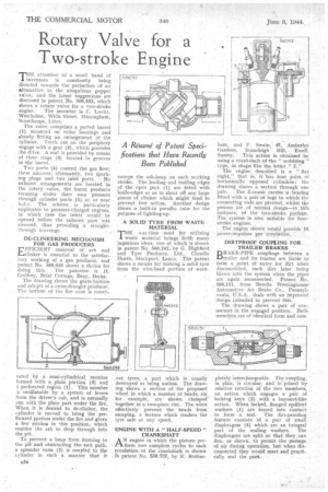
The valve comprises a ported barrel (1) mounted on roller bearings and glosely fitting an enlargement of the cylinder. Teeth cut on the periphery • engage with a geat (2), which provides the drive. A seal is provided by means of three rings (3) located in grooves in the barrel.
Two ports (4) control the gas flow; these uncover, alternately, two epark ing plugs and two inlet ports. No exhaust arrangements are located in the rotary valve, the burnt products escaping under their own pressure through cylinder ports (5) at or near b,d.c. The scheme is particularly applicable to pressure-charged engines, in which case the inlets would be opened before the exhaust port was covered, thus providint a straightthrough scavenge.
DE-CLINKERING MECHANISM FOR GAS PRODUCERS
EFFICIENT removal of ash and LL.clinker is essential to the satisfactory working of a gas producer, and patent No. 560,035 shows a device for doing this. The patentee is II. Godfrey, Briar Cottage, Bray, Berks.
The drawing shows the grate-bottom and ash-pit of a cross-draught producer. The bottom of the fire zone is consti tilted by a semi-cylindrical member formed with a plain portion (9) and a, perforated region (1). This member ,s oscillatable by a system of levers from the driver's cab, and is normally run with the plain part under the fire. When it is desired to de-clinker, the cylinder is moved to bring the perforated pprtion under the fire and given a few strokes in this position, which enables the ash to drop through into the pit.
To prevent a heap from forming in the pit and obstructing the exit path, a spreader vane (2) is coupled to the cylinder in such a manner that it sweeps the ash-heap on each working stroke. The leading and trailing edges of the open part (1) are fitted with knife-edges so as to shear off any large pieces ofclinker which might tend to prevent free action. Another design shows a built-in paraffin tube for the purpose of lighting-up.
A SOLID TYRE FROM WASTE MATERIAL
rrHE war-time need for utilizing 1•waste material brings forth many ingenious ideas, one of which is shown in patent No. 560,242; by G. Highfield and Tyre Products, Ltd., Cheadle Heath, Stockport, Lancs. The patent shows a means for making a solid tyre from the wire-bead portion of worn out tyres, a part which is usually• destroyed as being useless. The drawing shows a section of the proposed wheel in which a number of beads, six for example, are shown clamped together in a two-piece rim. The wires effectively prevent the beads from escaping, a feature which renders the tyre safe at any speed.
ENGINE WITH A " HALF.SPEED " CRANKSHAFT
AN engine in which the pistons perform two complete cycles to each revolution of the crankshaft is shown in patent No. 559,737, by K. Rother
ham, and F. Swain; 41, Arnberley Gardens, Stoneleigh Hill, Ewell, Surrey. This action is obtained by using a crankshaft of the '? wobbling " type, in shape like the letter Z."
The engine described is a "flat .eight," that is, it has four pairs of horizontally opposed cylinders; the drawing shows. a section through one pair. The Z-crank carries 'a -bearing fitted with a pair of lugs to which the connecting rods are pivoted, whilst the pistons are of normal design—in this instance, of the two-stroke pattern. The system is also suitable for few stroke engines. _ The engine shown • would provide 16 power-impulses per revolution.
DIRTPROOF COUPLING FOR TRAILER BRAKES DRAKE-PIPE couplings between a L./trailer and its tractor are liable to form a point of entry for dirt when disconnected, such dirt later being blown into the system when the pipes are again reconnected. Patent No. 560,151, from Bendix Westinghouse Automotive Air Brake Co., Pennsylvania, 'U.S.A., deals with an improved design intended to prevent this.' The drawing shows a pair of connectors iii the engaged position. Both members are of identical form and corn pletely interchangeable. The coupling, in plan, is circular, and is joined by relative rotation of the two members, an action which engages a pair of locking keys (2) with a bayonet-like action. When locked, flanged resilient washers (1) are forced into contact to form a seal. The dirt-proofing feature consists of a pair of small diaphragms (3) which are an integral part of the sealing washers. The diaphragms are split so that they can flex, as shown, to permit the passage of air during operation, but when disconnected they would meet and practi cally seal the port. •