


ispension 6
Page 54
If you've noticed an error in this article please click here to report it so we can fix it.
E PRIMARY air circuit for air ings fitted to commercial ides is shown in Figure 1. It be seen that the air supply les from the same source as tfor the air brakes. Obviously essential that air used for the pension system does not igerously deplete that
uired for braking. On the unds of safety a priority rging valve is sited in the ply line immediately in front le check valve. It ensures the Drake circuit receives priority supply over the suspension uit in the event of a failure of ;mponent or pipe-line vnstream of it. The valve is -set so that the braking circuit ays receives priority if the air ssure falls below 65psi 82bar).
check valve is sited at the t connection to the reservoir is included in order to iate the reverse leakage of ipressed air through the ipressor when the engine is running.
filter, which incorporates a rse polythene replaceable nent, is included in the circuit tveen the reservoir and the Iling valve for the purpose of arating out major taminants present in the air ply stream.
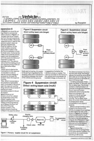
gure 2 shows an air pension circuit for a direct ng single beam axle (This aration, together with ires 3 and 4 appears by kind -nission of the Engineering up of Messrs Dunlow, the cers of the Pneuride
pension system.) The ftration shows a levelling 'e fitted in the pipe line which feeds each air spring. Air supply to the spring is regulated by the levelling valve and it maintains a set distance between the frame of the vehicle and the ground, irrespective of whether the vehicle is empty or loaded. The valve is mounted on the frame of the vehicle and is connected, by suitable linkage, to the axle. As the distance between the frame and the axle varies, the linkage adjusts the levelling valve which then adds air to the spring if the frame is too low or exhausts air from it if it is too high.
Levelling valves are of two types, the delay, or damped, and the no-delay type. The former contains a dashpot/piston oil chamber arrangement between the air input and output mechanism which ensures that there is no change in air pressure in the air springs during normal highway running. The no-delay valve does not contain this facility and in consequence reacts immediately to any signal it receives.
Where a single levelling valve is fitted in the centre of the vehicle, to control the air springs on each side of an axle, as is shown in Figure 3, an isolator valve is substituted for the T junction in the supply line. When the load on the two springs is unequal, the difference in near to offside load distribution is balanced out by the isolator valve to a common load pressure.
Figure 4 shows the
suspension for air springs fitted to a tri-axle vehicle, suitable, one would think, for a semi-trailer, operating at 38 tonnes.