


A Résumé of Recently Published Patent Specifications
Page 52
If you've noticed an error in this article please click here to report it so we can fix it.
Novelty in Injection Pump Design
AN unorthodox design of injection pomp is shown in patent No. 598,454, by Ca!list°, a French concern, of Neuilly-sur-Seine. The most unusual feature is the means used for controlling the output of the pump.
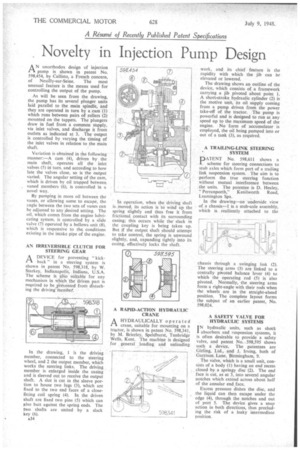
As will be seen from the drawing, the pump has its several plunger units laid parallel to the main spindle, and they are operated in turn by a cam (1) which runs between pairs of rollers (2) mounted on the tappets. The plungers draw in fuel from a common supply, via inlet valves, and discharge it from outlets as indicated at 3. The output is controlled by varying the timing of the inlet valves in relation to the main shaft.
Variation is obtained in the following manner:—A cam (4), driven by the main shaft, operates all the inlet valves (5) in' turn, and according to how late the valves close, so is the output varied. The angular setting of the cam, which is driven by oil trapped between, vaned members (6), is controlled in a novel way.
By pumping in more oil between the vanes, or allowing some to escape, the angle between the two sets of vanes can be adjusted to any desired setting. The oil, which comes from the engine lubricating system, is controlled by a slide valve (7) operated by a bellows unit (8), which is responsive to the conditions existing in the intake pipe of the engine.
AN IRREVERSIBLE CLUTCH FOR STEERING GEAR A DEVICE for preventing "kickCl back" in a steering system is shown in patent No. 598,318, by W. Starkey, Indianapolis, Indiana, U.S.A. The scheme is also suitable for any mechanism in which the driven part is required to be yievented from disturbing the driving member.
In the drawing, I is the driving member, connected to the steering wheel, and 2 the output member, which works the steering links. The driving member is enlarged inside the casing and is sleeved out to receive the output shaft. A slot is cut in the sleeve portion to house two lugs (3), which are fixed to the two end faces of a closefitting coil spring (4). In the driven shaft are fixed two pins (5) which can also butt against the spring ends. The two shafts are united by a slack key (6).
a34
In operation, when the driving shaft is moved, its action is to wind Up the spring slightly and thus free it from frictional contact with its surrounding casing; this occurs while the slack in the coupling key is being taken up. But if the output shaft should attempt to take control, the spring is unwound slightly, and, expanding tightly into its casing, effectively locks the shaft.
A RAPID-ACTION HYDRAULIC CRANE A HYDRAULICALLY operated rA crane, suitable for mounting on a tractor, is shown in patent No. 598,341, by M. Brierley, Speldhurst, Tunbridge Wells, Kent. The machine is designed for general loading and unloading
work, and its chief feature is the rapidity with which the jib can be elevated or lowered.
The drawing shows an outline of the device, which consists of a framework carrying a jib pivoted about point 1. A short-stroke hydraulic cylinder (2) is the motive unit, its oil supply coming from a pump driven from the power take-off of the tractor. The pump is powerful and is designed to run at any speed up to the maximum speed of the engine. No form of accumulator is employed, the oil being pumped into or out of a tank (3), as required.
A TRAILING-LINK STEERING SYSTEM
PATENT No. 598,611 shows a
scheme for steering connections to stub axles which form part of a trailing link suspension system. The aim is to perform the true steering function without mutual interference between the units. The patentee is D. Healey, " Perranporth," Kenilworth Road, Leamington Spa.
In the drawing—an underside view of a chassis-1 is a stub-axle assembly, which is resiliently attached to the chassis through a swinging link (2). The steering arms (3) are linked to a centrally pivoted balance lever (4) to which the operating rod (5) is also pivoted. Normally, the steering arms form a right-angle with their rods when the wheels are in the straight-ahead position. The complete layout forms the subject of an earlier patent, No. 598,024.
A SAFETY VALVE FOR HYDRAULIC SYSTEMS
IN hydraulic units, such as shock 1 absorbers and Fuspension systems, it is often desirable to provide a safety valve, and patent No. -598,595 shows such a device. The patentees are Girling, Ltd., and J. Irving, both of Garrison Lane, Birmingham, 9.
The valve, which is a small unit, consists of a body (1) having an end recess closed by a springy disc (2). The end face is cut, as at 3, into several angular notches which extend across about half of the annular end face.
Excess pressure dishes the disc, and the liquid can then escape under the edge (4), through the notches and out of port 5. The device gives a snap action in both directions, thus precluding the risk of a leaky intermediate position.