


By L. J. COTTON, M.I.R.T.E. W ITH the permission of Mr.
Page 32
Page 33
Page 34
If you've noticed an error in this article please click here to report it so we can fix it.
D M Sinclair, general manager of the Birmingham and Midland Motor Omnibus Co., Ltd. "The Commercial Motor" is able to follow. up with a full road
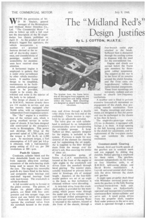
test the description of the S8 singledecker bus chassis published on April 21 As the product of one of Britain's biggest bus operators, the vehicle incorporates a number o f practical features devised as the result of day-to-day experience, and considerations of passenger comfort and accessibility for maintenance have received close attention A horizontal engine is employed--La pattern that is under close surveillance by other vehicle manufacturers. It enables frame design to be simplified, maintenance to be facilitated,;Additional passenger space to be provided, weight to be evenly distributed and noise in the interior of the body to be reduced.
This design of chassis is not new to B.M.M.O., because already there are 114 models in service, and one has recently been equipped after 70,000 miles, with an experimental independent-front-suspension system.
The " flat " engine is a modification of the vertical unit, which is giving excellent service in earlier types of chassis. It has been designed aid constructed at the company's works in Birmingham. This power unit develops 105 b.h.p. at the governed speed of 1,700 r.p.m. and the torque is 343 lb.-ft. at 1,200 r.p.m. At maximum torque, a fuel consumption of 0.35 pint per b.h p. is obtained, with a fuel-injectionpump setting of 15.3 c.c. per 200 revolutions at 300 r.p.m.
Push-fit Liners
Crankcase, cylinder block and the twin detachable heads are formed from separate alloy-iron castings, extensions of the main-bearing studs being used to secure the block to the case. The engine has renewable push-fit dry liners fitted to the bores, and composite main bearings and steel-shell big-end bearings lined with lead-bronze. The crankshaft is nitride-hardened.
A full toroidal cavity is formed in the piston crowns. The pistons, of Heplex tin plated silicon alloy pattern, are fitted with four compression and two scraper rings, one above and one below the gudgeon pins. Push-rods and rocker levers operate the overhead valves from the camshaft housed in the crank A30 case, and driven through a double roller chain from the fore end of the crankshaft. Chain tension is regu lated by an adjustable sprocket. The valve gear on each cylinder head is enclosed by an independent aluminium-alloy cover incorporating the air-intake passage. A large Talflow air filter, specially designed for the engine, is included in the system. Provision is made for easy removal of the element for cleaning and for replenishing the oil supply. Air is supplied to the filter through ducts from the canopy over the driver's cab, thus ensuring the intake of clean air.
The fuel-injection pump, of Simms or C.A.V. manufacture, is located at the front of the engine at right angles to the crankshaft and driven from the camshaft through bevel gearing. The injector pipes, suitably bracketed to prevent movement or breakage, Ste of unequal length. Injectors of the four-holenozzle pattern are set at an angle in the head, so that turbulence is obtained without valve shrouding.
A twin-belt drive from the crankshaft pulley is provided for the water pump, which passes water through the under side of the cylinder block and through drilled passageways to the valve and injector housing. Water is returned to the radiator, located at the front of the chassis, through a
four-branch outlet pipe attached to the heads. Sufficient heat is dissipated through the cooling system to dispense with the need for the conventional fan.
Engine and clutch are carried below the frame side members by threepoint rubber suspension The support at the rear is in the form of an annulus around the clutch housing, and the front -units are large-diameter rubber-tometal bonded components. These front mountings are extremely resilient and are located to absorb low-frequency oscillations.
A snubber unit is fitted to prevent excessive fore-and-aft movement on engagement of the clutch, thus pro..viding smooth acceleration from rest. Engine mountings and attachments are designed so that the power unit can be exchanged in the chassis in less than 21 hours.
The single-dry-plate-type clutch, 15i ins, in diameter, is equipped with facings A in. thick. A large opening in the bell housing provides access to the clutch for adjustment, and for replacement of the two-piece starter ring; and ventilates the clutch. mechanism Constant-mesh Gearing
Second, third and fourth speeds of the gearbox are in .constant mesh and are engaged by sliding dog clutches. Helical gearing is employed for these ratios. The gearbox, mounted independently on the frame on four Silentbloc units, is of B.M.M.O. split-casing design and David Brown manufacture. A Layrub universal-jointed shaft transmits the drive between the clutch and gearbox A single open propeller shaft fitted with Whittaker universal joints connects the gearbox to the fully floating overhead-worm-driven back axle.
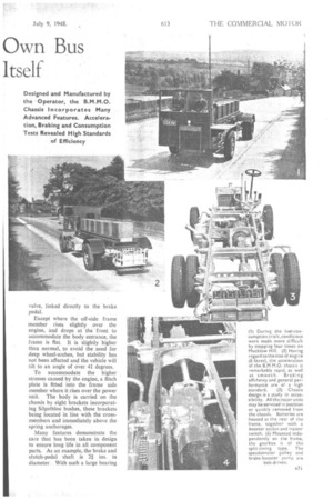
The brakes are hydraulically operated and incorporate a Lockheed continuous-flow master-cylinder and servo unit. A small pump, driven from the propeller shaft, supplies fluid under pressure to the servo unit, which is operated through a control valve, linked directly to the brake pedal
Except where the off-side frame member rises slightly over the engine, and drops at the front to accommodate the body entrance, the frame is flat. It is slightly higher than normal, to avoid the need for deep wheel-arches, but stability has not been affected and the vehicle will lilt to an angle of over 41. degrees.
To accommodate the higher stresses caused by the engine, a flitch plate is fitted into the frame side member where it rises over the power unit. The body is carried on the chassis by eight brackets incorporating Silcntbloc bushes, these brackets being located in line with the crossmembers and immediately above the spring anchorages.
Many features demonstrate the care that has been taken in design to ensure long life in all component parts. 'As an example, the brake and clutch-pedal shaft is 24 ins, in diameter. With such a large bearing
area there is little 'chance of wear ever becoming apparent.
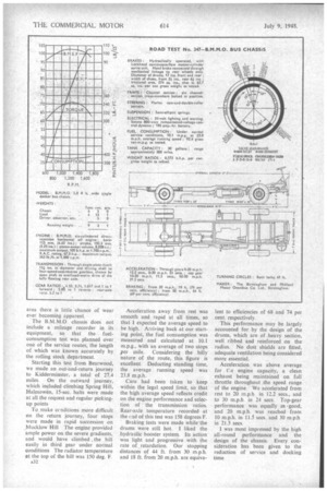
The B.M.M.0 chassis does not include a mileage recorder in its equipment, so that the fuelconsumption test was planned over one of the service routes, the length of which was known accurately by the rolling stock department.
Starting this test from Bearwood, we made an out-and-return journey to Kidderminster, a total of 27.4 miles. On the outward journey, which included climbing Spring Hill, Halesowen, 15-sec. halts were made at all the request and regular pickingup points To make ccmlitions more difficult on the return journey, four stops were made in rapid succession on _Mucklow Hill The engine provided ample power on the severe gradients, and would have climbed the hill easily in third gear under normal conditions The radiator temperature at the top of the hill was 150 deg. F. A32
Acceleration away from rest was smooth and rapid at all times, so that I expected the average speed to be high. Arriving back at our starting point, the fuel consumption was measured and calculated at 10.1 m.p.g., with an average of two stops per mile. Considering the hilly nature of the route, this figure is excellent. Deducting standing time, the average running speed was 23.8 m.p.h.
Care had been taken to keep within the legal speed limit, so that the high average speed reflects credit on the engine performance and selection of the transmission ratios. Rear-axle temperature recorded at the cnd of this test was 158 degrees F.
Braking tests were made while the drums were still hot. I liked the hydraulic booster system. Its action was light and progressive with the rate of retardation. Our stopping distances of 44 ft. from 30 m.p.h. and 18 ft. from 20 m.p.h. are equiva
lent to efficiencies of 68 and 74 per cent. respectively.
This performance may be largely accounted for by the design of the drums, which are of .,heavy section, well ribbed and reinforced on the radius. No dust shields are fitted, adequate ventilation being considered more essential.
Acceleration was above average for t!:e. engine capacity, a clean exhaust being maintained on full throttle throughout the speed range of the engine. We accelerated from rest to 20 in.p.h. in 12.2 secs., and to 30 m.p.h in 24 secs. Top-gear performance was equally as 'good, and 20 m.p.h. was reached from 10 m.p.h. in 11.5 secs. and 30 m.p.h in 21.5 sees.
I was most impressed by the high all-round performance and the design of the chassis. Every consideration has been given to the reduction of service and docking time.