 1
1 2
2 3
3 4
4 5
5 6
6 7
7 8
8 9
9 10
10 11
11 12
12 13
13 14
14 15
15 16
16 17
17 18
18 19
19 20
20 21
21 22
22 23
23 24
24 25
25 26
26 27
27 28
28 29
29 30
30 31
31 32
32 33
33 34
34 35
35 36
36 37
37 38
38 39
39 40
40 41
41 42
42 43
43 44
44 45
45 46
46 47
47 48
48 49
49 50
50 51
51 52
52 53
53 54
54 55
55 56
56 57
57 58
58 59
59 60
60 61
61 62
62 63
63 64
64 65
65 66
66 67
67 68
68 69
69 70
70 71
71 72
72 73
73 74
74 75
75 76
76 77
77 78
78 79
79 80
80 81
81 82
82 83
83 84
84 85
85 86
86 87
87 88
88 89
89 90
90 91
91 92
92 93
93 94
94 95
95 96
96 97
97 98
98 99
99 100
100 101
101 102
102 103
103 104
104 105
105 106
106 107
107 108
108 109
109 110
110 111
111 112
112 113
113 114
114 115
115 116
116 117
117 118
118 119
119 120
120 121
121 122
122 123
123 124
124 125
125 126
126 127
127 128
128 129
129 130
130 131
131 132
132 133
133 134
134 135
135 136
136 137
137 138
138 139
139 140
140 141
141 142
142 143
143 144
144 145
145 146
146 147
147 148
148 149
149 150
150 151
151 152
152 153
153 154
154 155
155 156
156 157
157 158
158 159
159 160
160 161
161 162
162 163
163 164
164 165
165 166
166 167
167 168
168 169
169 170
170 171
171 172
172 173
173 174
174 175
175 176
176 Originality in UNIVERSAL-JOINT DESIGN
Page 84
If you've noticed an error in this article please click here to report it so we can fix it.
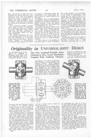
The New Jonkhoff Flexible Joint Claimed to Give Great Flexibility Coupled With Uniform Velocity.
ARECENT patent by Mr. H. M. Jonkhoff, of Holmsdale, South Eden Park Road, Beckenham, Kent, is of considerable interest to those connected with road transport matters. It relates to a universal driving coupling which can also be applied as a flexible type of journal bearing, capable of doing duty as a self-aligning thrust bearing at the same time. .
Two important defects in connection with the conventional type of universal joint have long been recognized. Among the claims made for the Jonkhoff joint is that it overcomes these ; we refer to the necessity of having the first and third shafts parallel in a threeshaft assembly, and to the uneven velocity of transmission which is especially noticeable when four pivot points are used in any particular joint.
One purpose to which the coupling can be put is that of a bearing for a road wheel where power has fn he
E26 transmitted to the wheel, at the same time permitting lateral deflection for steering purposes. Other suggested applications are for clutch-centre bearings—the thrust-taking properties being here exploited—or for making the steering-wheel mounting on the column of an adjustable type. As shafts can be connected when the angle between them is 22i degrees or more, the coup; lings can be made up with short shafts to form a flexible cable or chain for power transmission.
Turning to the constructional aspect of the Jonkhoff joint and referring to the illustrations, it will be seen that there is a spherical bearing fixed, by splines or other media, to one shaft. Coupled to the other shaft is a housing containing a spherical bearing surface of greater radius than that of the ball attached to the first-mentioned shaft. Between the two is an even number of mating projections or pegs. These are similar in form to smooth-faced bevel wheels and half of them take their bearing in the inner body or ball and half in the outer housing. Pegs in the former category are radiused on the head to bear upon the spherical surface, whilst those which are mounted in the outer
housing are machined on the heads to -work upon the ball attached to the shaft.
It will be seen that the pegs form a spherical bearing of considerable size, and two or more of them always maintain contact—thus transmitting the drive—whatever angle there may be between the inner and outer members of the joint. In the case of a four-peg design the velocity ratio will be constant at four periods per revolution only slight deviations will occur as the drive is taken up or released by pairs of pegs.
When the two shafts coupled by a jonkhoff joint are coaxial the efficiency is 100 per cent. It is claimed that there is only a slight diminution of efficiency when the shafts are inclined one to another, or when the joint is used as a bearing. The loss represents the work done in the spherical bearing, which is, of course, adequately lubricated so as to prevent undue wear.