


Patents Completed.
Page 20
If you've noticed an error in this article please click here to report it so we can fix it.
LUBRICATOR.—Panhard and Levassor.—No. 2,334/1908, dated (under Convention) 25th March, 1907.—According to this invention the suction produced in the engine inlet pipe, or carburetter, is utilised for controlling the supply of lubricant to the engine. An oil reservoir (A) communicates with the sight feed chamber (D) by means of a bent conduit (H), passage (C) and nozzle (F) ; the nozzle being controlled by a needle valve (G). The chamber (D) is provided with a glass window (E) and, at its lower end, communicates with a pump (not shown) which draws the lubricant from the cham her (D) and forces it into the part to be lubricated. At the top of the chamber is a passage (K) which is in communication with the engine inlet pipe or the carburetter so that the suction, or partial vacuum, therein is extended to the chamber. The vacuum causes the oil to flow through the pipe (H) and the passage (C), and past the inlet valve (G) where it drips into the chamber. It will be seen that, as the speed of the engine varies, the suction in the chamber will vary correspondingly, thus drawing a greater, or less, amount of oil from the reservoir (A) through the nozzle (F).
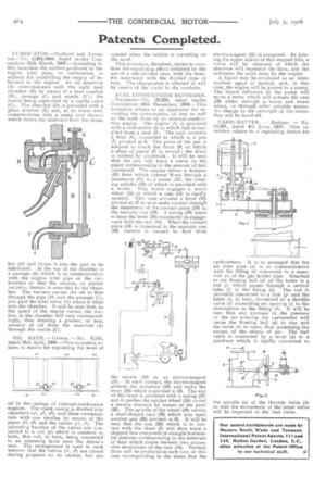
OIL BATIL — Grimm. — No. 8,555, dated 16th April, 1908.—This invention relates to means for regulating the level of
oil in the casings of internal-combustion engines. The crank casing is divided into chambers (al, a2, a3), and these communicate with one another by means of the pipes (bl, b2) and the valves (cl, c2). The operating handles of the valves are connected to a rod (d) which is common to both, this rod, in turn, being connected to an operating lever near the driver's seat. The arrangement is used in such manner that the valves (cl, c2) are closed during progress on an incline, but are
opened when the vehicle is travelling on the level.
This invention, therefore, claims to combine the equalising effect obtained by the use of a sub-divided case, with the benefits associated with the divided type of tray. The change-over is effected at will by means of the cocks in the conduits.
FUEL CONSUMPTION RECORDER. —Nielausse—No, 26,624, dated (under Convention) 26th December, 1906.—This invention relates to an apparatus for recording the consumption of fuel as well as the work done by an internal-combustion engine. The engine (1) is provided with a carburetter (2) to which fuel is supplied from a tank (3). The tank contains a float (4), connected to which is a pen (7) pivoted at 6. The point of the pen is adapted to touch the drum (9) on which a sheet of paper (8) is wound ; the drum is rotated by clockwork. It will be seen that the pen will trace a curve on the paper corresponding to the amount of fuel consumed. The engine drives a dynamo (10) from which current flows through a resistance (11) to a meter (12), the rotating spindle (13) of which is provided with a worm. This worm engages a worm wheel (15) to which a cam (14) is rigidly secured. This cam actuates a lever (16) pivoted at 17 so as to make contact through the immersion of the contact piece (18) in the mercury cup (19). A spring (20) tends to keep the lever (16) constantly in engagement with the cans (14). When the contaet piece (18) is immersed in the mercury cup (19) current is caused to flow from
the source (22) to an electro-magnet (21). At each contact, the electro-magnet attracts the armature (23) and rocks the lever (24) which is pivoted at 25. The end of this lever is provided with a spring (27) and it pushes the ratchet wheel (28) round a certain distance by means of the pawl (26). The spindle of the wheel (28) carries a snail-shaped cam (29) which acts upon another pen (33) pivoted at 31. It will be seen that the pen (33) which is in contact with the sheet (8) will thus trace a stepped line composed of straight horizon. tal portions corresponding to the intervals of time which elapse between two successive revolutions of the cam (14). Vertical lines will be produced at each turn of this cam corresponding to the times that the electro-magnet (21) is energised. By joining the upper apices of this stepped line, a curve will be obtained of which the abscissa will represent the time, and the ordinates the work done by the engine.
A liquid may be employed as an intermediate agent if desired, and, in this case, the engine will be geared to a pump. The liquid delivered by the pump will move a meter which will actuate the cam (29) either through a worm and worm wheel, or through other suitable means. No change in the principle of the invention will be involved.
CARBURETTER. — Dolman, — No, 12,891, dated 4th June, 1907.—This invention relates to a regulating device for
carburetters. It is so arranged that the air inlet pipe (a is in communication with the fitting (b) connected to a reservoir (c) of the gas holder type. Attached to the floating bell (d) of the latter is a rod (e) which passes through a central tube (f) in the fitting (b). The rod is pivotally connected to a link (g1 and the latter is, in turn, connected to a throttle valve (h) controlling an opening (i) to the atmosphere in the fitting (h). It will be seen that any increase in the pressure of the air entering the carburetter will cause the floating bell (d) to rise and the valve (4) to open, thus permitting the escape of the excess of air. The fuel valve is connected by a lever (15) to a quadrant which is rigidly connected to the spindle (n) of the throttle valve (h)so that the movements of the latter valve will be imparted to the fuel valve.