 1
1 2
2 3
3 4
4 5
5 6
6 7
7 8
8 9
9 10
10 11
11 12
12 13
13 14
14 15
15 16
16 17
17 18
18 19
19 20
20 21
21 22
22 23
23 24
24 25
25 26
26 27
27 28
28 29
29 30
30 31
31 32
32 33
33 34
34 35
35 36
36 37
37 38
38 39
39 40
40 41
41 42
42 43
43 44
44 45
45 46
46 47
47 48
48 49
49 50
50 51
51 52
52 53
53 54
54 55
55 56
56 57
57 58
58 59
59 60
60 61
61 62
62 63
63 64
64 65
65 66
66 67
67 68
68 69
69 70
70 71
71 72
72 73
73 74
74 75
75 76
76 77
77 78
78 79
79 80
80 81
81 82
82 83
83 84
84 85
85 86
86 87
87 88
88 89
89 90
90 91
91 92
92 93
93 94
94 95
95 96
96 97
97 98
98 99
99 100
100 101
101 102
102 103
103 104
104 105
105 106
106 107
107 108
108 109
109 110
110 111
111 112
112 113
113 114
114 115
115 116
116 117
117 118
118 119
119 120
120 121
121 122
122 123
123 124
124 125
125 126
126 127
127 128
128 129
129 130
130 131
131 132
132 133
133 134
134 135
135 136
136 137
137 138
138 139
139 140
140 141
141 142
142 143
143 144
144 145
145 146
146 147
147 148
148 149
149 150
150 151
151 152
152 153
153 154
154 155
155 156
156 157
157 158
158 159
159 160
160 161
161 162
162 163
163 164
164 165
165 166
166 167
167 168
168 169
169 170
170 171
171 172
172 A Cylinder-liner Manipulator
Page 146
If you've noticed an error in this article please click here to report it so we can fix it.
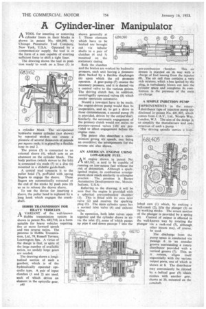
ATOOL for inserting or removing cylinder liners in their blocks is shown in patent No. 684,090, by Chicago Pneumatic Tool Company, New York, U.S.A. Operated by a compressed-air supply, the tool is in the form of a ram capable of exerting sufficient force to shift a tight liner.
The drawing shows the tool in position ready to work on a liner (1) in
a cylinder block. The air-operated hydraulic master cylinder (not shown) by repeated strokes can create a pressure of several thousands of pounds per square inch; it is piped by a flexible hose to end 2.
The piston (3) is connected to an external sleeve (4), which acts as an abutment on the cylinder block. The body portion (which moves to the left) is connected via studs (5) to a disc (6) mounted in a stidable guide-bush.
A central stud connects it to the puller head (7), protided with .spring
fingers to engage the sleeve. These fingers are automatically retracted at the end of the stroke by push pins (8) so as to release the drawn sleeve.
To use the device for inserting a sleeve, the puller head is replaced by a Jong hook which engages the crankshaft.
HOBBS TRANSMISSION FOR HEAVY VEHICLES
A VARIANT of the well-known Hobbs transmission system is shown in patent No. 682,710, in a form suitable for heavy vehicles requiring five or more forward speeds and two reverse ratios. The patentee is Hobbs Transmission, Ltd., 78, Russell Terrace, Leamington Spa. A virtue of the design is that, in spite of the large number of available ratios, no unduly large gears are needed,
The drawing shows a longi
tudinal section of such a gearbox, which is of the hydraulically operated epicyclic type. A pair of input clutches (1 and 2) are used, each of which drives an element in the epicyclic gear,
a40 shown generally at 3. Those elements which have to be braked are brought out via tubular shafts to a pair of clutches (4 and 5) mounted on the stationary casing.
Both the clutches and the brakes are worked by hydraulic pressure, each unit having a pressureplate backed by a flexible diaphragm (6) upon which the oil pressure operates. A gear-pump (7) creates the necessary pressure, and it is ducted via a control valve to the various points. The driving clutch has, in addition, centrifugally operated valves (8) which render operation automatic.
Should a tow-start have to be made, the engine-driven pump would then be inoperative, and so, to get a drive in these circumstances, a second pump (9) is provided, driven by the output'shaft. Similarly, the automatic engagement of the primary clutch would not .occur, so pressure-opened valves (10) are provided to effect engagement before the engine runs. • The patent also describes a transmission giving six speeds, one being an overdrive; the arrangements for the reverse are also shown.
AN AMERICAN ENGINE USING LOW-GRADE FUEL
AN engine shown in -patent No. 683,162, is said to be capable of running on low-octane fuel without the risk of detonation. Although a sparkignited engine, its combustion arrangements show mucli similarity to oil engine practice. • The patentee is Barnes Automotive Developments inc.. Muncie, Indiana, U.S.A.
Referring to the drawing, it will be . seen that the engine is provided with a spherical pre-combustion chamber (1).• This is fitted with its own inlet valve (2) and receives the sparking plug (3). The main cylinder space has a normal inlet valve (4) and exhaust valve, In operation, both inlet valves open together and the cylinder draws in air via the inlet (5), some of which passes up pipe 6 and down passage 7 into the pre-combustion rharnber. This al • stream is injected on its way with a charge of fuel issuing from the injector (8). The air cell thus contains a very rich mixture, which when ignited by the plug, is turbulently blown out into the cylinder space and completes its combustion in the presence of the main air-charge, A SIMPLE INJECTION PUMP •
IMPROVEMENTS in the rotary-. I.distributor type of injection pump are disclosed in patent No. 681,405, Which comes from C.A.V., Ltd., Warple Way, London, W.3. The aim of the design is to. simplify the Manufacture and eon, struction of such a pump. • The driving spindle carries :1 tour.
lobedcam (1) which, by rocking a bell-crank (2), lifts the plunger (3) on its working stroke. The return motion of the plunger is provided by a spring
(4). Control of output is effected in the well-known way by rotating the plunger via a rack-rod (5), although. other means may, of course, be used.
The discharge from the pump space is conducted via passage 6 to an annular groove surrounding a rotary distributor provided with a vertical groove (7). This, as IL rotates, aligns itself sequentially with the various output ports, one of which is shown at 8. The distributor may conveniently be rotated by a •helical gear (9) which meshes with another gear. shown at 10. mounted on the