


Patents Completed.
Page 20
If you've noticed an error in this article please click here to report it so we can fix it.
Complete specifications of the following patents will be sent to any address in the United Kingdom by the Sale Branch, Patent Office, Holborn, upon receipt of eightpence per copy.
The AIlday Self-starter.
W. AlIday and C. E. Simms, No. 1633, dated 20th January, 1912.—This specification describes a starter of the type in which compressed air is admitted to a cylinder, and the piston red is provided with a rack engaging a pinion on the engine shaft, or geared to it. In the present construction the main air cylinder is lengthened to about twice the length of the piston stroke, and the piston and its rod are made hollow to form a secondary air cylinder. A small fixed piston is mounted on a tube inside the secondary air cylinder, and is so arranged that, after the power stroke, air can be admitted to the secondary cylinder, which is the primary piston, to return it to its initial position ready for another working stroke. The control of this mechanism is effected by a piston valve on a rod which is operated by the main piston. When the compressed-air supply is turned on, the main piston operates, and at the end of its stroke it shifts the valve, whereupon compressed air is admitted to the secondary cylinder. As soon as it starts on the return stroke. the valve is returned to its normal position by a spring.
The Latest Non-skid.
M. H. Cleaver, No. 139, dated 2nd January, 1912.—This invention consists of a detachable non-skid device for application to twin tires. It is designed with the object of being readily attached or removed without jacking up the wheel. A number of solid bars are secured together to form a chain round the wheel, and each alternate bar has cast on it arms that are curved on their under side to conform to the surface of the tire. On the upper face of this arm is a raised cross, one length of which lies transversely to the wheel and the other of which lies in the plane of the wheel, so that the read is gripped so as to prevent sideslip and to obtain tractive effort. The chain is loose on the wheel, and the sections are wedged between the twin tires by the pressure on them when they come in contact with the ground. When the weight is released the sections are free to move round the tire.
A Safety Petrol Tank.
H. Brinnme, No. 17,292, dated under International Convention, 22nd April, 1912.—According to this invention, a petrol tank is secured inside a. safety easing, as hown diazratriniatically, by a series of springs. The intervening space is packed with some absorbent material FIJCI, for instance, as wadding, which is rammed down or may even be compressed. If both the outer and inner casings are punctured, the wadding is forced into the hole and forms a plug, or if the hole is too big to be plugged, all the petrol is absorbed and none is
allowed to escape. A safety valve is also provided, which automatically closes the vessel in the event of the outlet pipe being fractured. A valve is provided to be operated by a short connecting link. and a pulley is arranged within the outlet. When the valve is off its seat, the link is on the upper side of the pulley ; a wire or cable is attached to the same part of the pulley and is led away through the outlet pipe to the carburetter, If the pipe is frac tured, tension is put on this wire, and the pulley is turned round and so closes the valve.
Saurer Side-tipping Wagon.
Adolph Saurer, Ltd., and G. Schlatter. No. 18,966, dated 19th August, 1912.— This specification describes an arrangement for tilting the body of a lorry. A lock is provided which, when in one position prevents the body's being tilted, and in other positions causes it to be tilted to one side or other according to the setting of the controlling lever. The body is carried on two globular bearings at, each side, and these are made somewhat more than hemispherical with a gap at the bottom ; they seat upon longitudinal shafts which are cut away so as to enter the narrow gap; in this way it will be seen that each shaft must be turned to a definite position to allow the bearing to be lifted off it. A controlling lever is connected to each of the shafts by suitable link-work, as shown in the aecompanying drawings, and this is so arranged that, when it, is in its vertical position, the body is locked in place. When the lever is thrown to the led thand side, the right-hand bearing is released, and the body can be tilted to the left. A similar action occurs when the body is to be tilted to the right. The tilting is performed by a. double screwjack, which operates on the central longitudinal line of the chassis and of the body, so that tilting can be obtained in either direction. Suitable spring grips are provided to secure the locking lever in any one of the three positions.
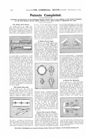
A Clutch for Dynamos.
H. M. Genese, No. 7165, dated 23rd March, 1912.—The accompanying drawing shows a clutch of the positive engagement type that is suitable for use with dynamos and similar accessories on inotorvans or in motor boats. The driving shaft on the right has a saucershaped disc mounted on it; stretched across the face of this plate is a flexible sheet of leather or similar material. A umber of holes are equally spaced round the leather disc, and these are engaged by pins carried on the other half of the clutch member, which is secured to the armature spindle, or other driven shaft on the left.