


The compression ignition engine, 5
Page 62
If you've noticed an error in this article please click here to report it so we can fix it.
IT WILL be remembered that in the last article in this series it was stated that an in-line fuel injection pump consisted of a number of separate pumping elements, one for each cylinder of the engine to which it is fitted. The amount of fuel to be injected into a cylinder will vary according to the load imposed on the engine at any particular time.
When pulling hard on full throttle much more fuel will be needed than when the engine is idling, say when the vehicle is stationary at traffic lights, waiting for them to change. As well as the need for the amount of fuel to be injected to be varied, the-quantity delivered to each cylinder must be the same and, of course, the fuel must be injected at precisely the correct moment when the piston is nearing TDC on the compression stroke.
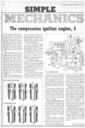
Fig 1, which together with the other illustrations appearing in this article are reproduced by kind permission of CAV Ltd, shows how the actual amount of fuel injected is varied. The plunger has an inclined groove or helix machined on it.
It can be rotated by a rack and control rod which meshes with a quadrant clamped to the control sleeve, which is slotted to engage the plunger toe. The rack engages with all the pumping elements so that any movement causes all the plungers to rotate simult,aneously to ensure an equal fuel delivery to each cylinder.
On the upward stroke of the plunger, fuel is pushed back through the barrel ports, (a) Fig 1, until the plunger closes the ports, (b) Fig 1. The fuel is then trapped and is only outlet is via the delivery valve at the top of the plunger barrel.
The pressure exerted causes the valve to lift and oil enters the pipe to the injector. As thrs-pipe is already filled with oil, fuel is
• injected into the combustion space via the injector. Fuel continues to be delivered until the helix uncovers the control or spill port (c) Fig 1, when fuel is pushed back into the gallery. By rotating the plunger a different part of the helix opens the spill port.
It will be seen, therefore, that although the actual stroke of the plunger is unaltered, its effective stroke, that is the distance it moves when actually delivering fuel, is varied. It is in this way that the engine speed and power is controlled. Fig 1 (c) (d)tand (a) show the approximate position of the helical edge for full-load, halfload and idling conditions. (f) shows the vertical channel opposite the right-hand port and in this position the fuel is by-passed to the common fuel chamber, during the plunger stroke, this being the "STOP position.
Fig 2 shows a section through a CAV Minimec pump which operates in a similar manner to that described, except that the plungers are rotated by forked levers and the plunger has a hole through it centre communicating with thi helix instead of a vertical chan nel. The centrifugal govern° weights are shown, togethe with a fuel lift pump which de livers fuel from the tank of thi vehicle to the injection pun'.
The delivery valve perform two functions. It acts as a non return valve preventing thl return of fuel from the higl pressure pipe-line when the spil port opens and it ensures a rapil drop in pressure in the pipe-Pin' as it closes so that there is sharp cut-off to injection. Thi prevents "dribbling" ou through the injector nozzl which would cause incornplet combustion, smoky exhaust an' high fuel consumption.
This rapid drop in pressure i achieved by the collar below th conical seat acting as a pisto and withdrawing a sma amount of fuel from the hig pressure line as the valve close!
More about compressio ignition engines in the ney article.
by Preceptor