Imparting "Feel" to Servo Brakes
Page 36

If you've noticed an error in this article please click here to report it so we can fix it.
A Resume of Patent Specifications That Have Recently Been Published
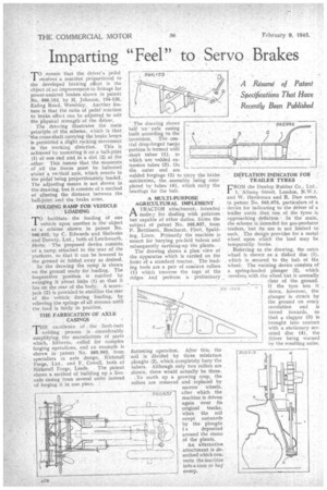
TO ensure that the driver's 'pedal ' receives a reaction proportional to • the developed braking effort is the object of an improvement in linkage for power-assisted brakes shown in patent No 566,153, by '.11. Johnson, 134-136, Ealing Road, Wembley, Another feature is that the ratio of pedal reaction to brake elite t can be adjusted to suit • the physical strength of the driver. The drawing illustrates the main principle of the scheme, which is that the cross-shaft carrying the brake levers is permitted a slight rocking movement in the working direction. This is achieved by mounting it on a ball-joint (1) at one end and in a .slot (2) at the .other: Thi.f means that the mornents Ofthe . forces must be • balanCed .ahut 'a vertical axis, Which results in the pedal being proportionately loaded. The adjusting means is not shown in the drawing, but it consists of a method of altering the distance between the ball-joint and the .brake arms,
FOLDING RAMP FOR VEHICLE LOADING .
TO facilitate the loading of one vehicle upon another is the ' object of a scheme shown in patent No. 566,032,by C. Edwards and Shelvoke and Drewry, Ltd., both of Letchworth, Herts. The proposed device consists of a ramp attached to the rear of the platform, so that it can be lowered to the ground Or folded away as desired.
In the drawing the ramp is shown on the ground ready for loading. The inoperative position is reached by swinging it about links (1) so that it lies on the rear of the body. A screwjack (2) is provided to stabilize the rear of the vehicle during loading, by relieving the springs of all stresses until the load is fairly in 'position.
THE FABRICATION OF AXLE CASINGS •
THE excellenCe of . the hash-butt welding process is considerably simplifying the manufacture of parts which, hitherto, called for complex forging operations, and an example is shown in patent No. 565,992, from specialists us axle design, Kirkstall Forge, Ltd., and F. Cowell, both cf
Kirkstall Forge, Leeds. The patent shows a method of building up a liveaxle casing from several units instead of forging it in one piece. •
The drawing shows half an axle casing built according to the invention. The central drop-forged banjo' ..-portion is formed with -short ttibea. (1), to which are welded extension tubes (2). On the outer end are welded forgings.' (3) to tarry the brake mechanism, the assembly being completed by tubes (4), which carry the bearings for the hub.
A MULTI-PURPOSE .AGRICULTURAL IMPLEMENT • A TRACTOR attachment, intended noain,y for dealing, with potatoes but capable *of Other duties, .forms the subject of patent No. 565,837, from P. Bettinson, Beechurst,. Fleet, Spalding, Lincs. Primarily the machine is meant for burying pre-laid tubers and subsequently earthing-up the plants. The drawing shows a plan view of the .apparatus which is carried on the front of a standard tractor. The leading tools are a pair of concave rollers (1) which traverse the tops of the ridges and perform a preliminary
flattening operation. After this, the soil is divided by three miniature ploughs (2), which completely burythe tubers. Although only two rollers are shown, there would actually be three.
• To earth up a growing crop, the rollers are removed and replaced by narrow wheels, after which the machine is driven again over its original tracks, when the soil swept outwards by the ploughs s deposited around the stems of the plants.
An alternative attachment is described which converts the machine into a corn or hay sweep. _ DEFLATION INDICATOR FOR TRAILER TYRES .
FROM the Dunlop Rubber Co., Ltd., 1, 'Albany -Street, London, N.W.1, and W. Hardman and R. Daw come, in patent No, 565,973, particulars of a • device for indicating to the driver of a trailer, outfit that one of the tyres is approaching deflation. In the main, the scheme is intended for gas-producer trailers, 'but its use is not limited to such. The design provides for a metal wheel upon which the load may be temporarily, borne.
Referring to the drawing, the extra wheel is shown as a dished disc (1), . which is secured to the hub of the wheel. The warning device consists of a spring-loaded plunger (2), which revolves with the wheel but is normally :lea" of the ground. If the tyre lets it , clown, however, the plunger is struck by the ground on every revolution and is forced inwards, so that a clapper (3) is brought into contact with a stationary serrated disc (4), the driver being warned by the resulting noise.


