


HEATING AND VE TIL PASSENGER VEHICLES
Page 26
Page 27
Page 28
If you've noticed an error in this article please click here to report it so we can fix it.
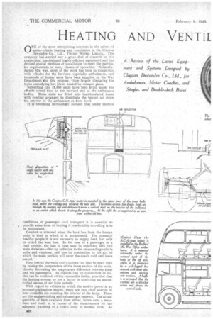
A Review of the Latest Equipment and Systems Designed by Clayton Dewandre Co., Ltd., for Ambulances, Motor Coaches, and Single. and Double-deck Buses The Comfort and Health of Passengers in Public-service Vehicles Demand an Ample Supply of Fresh Air at Controlled Temperature With the Minimum of Draughts
ONE of the most enterprising concerns in the sphere of motor-vehicle -heating and ventilation is the Clayton Dewandre. Co., Ltd., Titanic Works„ Lincoln., This company has carried out a great dealof research in this connection, has designed highly, efficient equipment and has devise.d special methods of installation to meet the particular requirements of many classes of operation. Naturally, during this war, most of the work has been in connection , with vehicles for the Services, especially ambulances, and thousands of heater units have been supplied to the War Department or this purpose, these largely displacing the types embodying hot plitei heated by exhaiust gases.
Something like 15,000 units have been fitted -under the off-side raised floor at the forward end of the ambulance bodies. These units are fitted into heat-insulated boxes with cowling arranged to distribute the heated -air down the .interior of the ambulance at floor level. *
• It is becoming increasingly realized that under modern
conditions .of passenger road transport it is essential to provide some form of heating if comfortable travelling is to be maintained.
Comfort is attained when the heat loss from the human body is that to which it is accustomed. For normally healthy people it is not necessary to supply heat, but only to retard the heat loss. In the case of a passenger in a road vehicle, the loss of heat may be separated into two main divisions—that by radiation to the surrounding vehicle walls and windows, and loss by conduction to the air, of which the main portion will enter the coach cold and leave heated.
Heat lost to the walls and windows can best be dealt with by raising the temperature of the inner surface of the walls, thereby decreasing the temperature difference between these and the passengers. As regards loss by conduction to air, this can be confined within, reasonable limits, provided that the heating system be not a factor in admitting an uncontrolled excess of air from outside.
With regard to vehicles in which the motive power is an internal-combustion -engine, there are two chief sources of heat available for warming the interior of the body. These are the engine-cooling and exhaust-gas systems. The actual quantity of heat available from either, taken over a mean titna and load, is in excess of the requirements for the adequate warming of a coach body of normal form. As regards that available from the cooling water, the temperature of-the heating medium is comparativelylow, and by the introduction of a suitable' radiating surface, air can be heated ivithout in any way changing its character. Automatic control of the heat flow can also readily be obtained by diversion -from the usual radiator, using thermostatic means.
Where • the heat is from the exhaust gases, the amount available fluctuates to a marked degree with engine load, and the resulting large changes in temperature do not lend themselves readily to automatic or even manual control. In certain instances the temperature reached may be very high. anti there is a danger of " burning " or -contamination of the interior air, with disagreeable consequences.
All types of Clayton heater utilize the hot water from -the engine-cooling system as their source of heat. This is circulated' through aspecially designed, high-efficiency heating • element, and air is drawn over the surface by a built-in Ian driven by an electric motor. The warnied air is then discharged into the vehicle body at a reasonable velocity, whilst thermostatic means control the temperature of the water and that of the interior air.
The standard unit is of circular form, the air being drawn in through the grille around the periphery oi the heater and delivered down the centre of the gangway, without impinging directly on to the passengers. Its output is rated at 15,000 B.T.I.I.s per hour at a temperature difference of 120 degrees F.; that is, the difference in temperature between the air entering the heater and the mean temperature of the water, circulating through the element. For example, with air, enferino•° at 40 degrees F., and a mean water temperature of 160 degrees F., the heater will dissipate its.rated heat capacity and raise the interior temperature to about 55 degrees F., provided uncontrolled quantities of cold air be not admitted,
The electrical-energy consumption of the fan motor is about 20 watts. .A manually controlled switch is used for cutting out of circuit this motor as required.
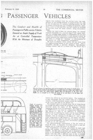
For long-distance travelling, particularly' at night and during cold weather, a dual °heater installation is recommended. In this case a standard unit is mounted on the centre of the forward bulkhead and a. second, which is of similar form but with a different type of Ian, is located under a seat at the rear. This fan draws air into the circa Jar front of the unit, which is then at the top, and discharges it radially, thus permitting air circulation clown the centre of the gangway at floor level towards the front. This combination results in "a much higher output of heat and a more :uniform air.teenperature throughout the body. With an atmospheric temperature of 32 degrees F., a coach. with an interior temperatare-of 65 degrees F. is normal.
In corijunction, with this dual system, the company recommends the fitting of an air thermostat to provide accurate control of the internal temperature..
In the early days of the' ciayton heater it was realised that some form of temperature control for the circulating water was essential. This resulted in the designing of a therinostatic diverter--rn essence, a valve under the control of a thermal element and located between the water outlet from the cylinder, jacket and the radiator. It operates as follows:—At below 170 degrees F., the valve is closed and the water circulates through the heater unit. At above 'this temperature the valve begins to open and by-passes some of the cooling water to the main radiator. At about 190 degrees, the valve isefully open, and thfi. diverter ceases to influence the flow to the radiator.
The .thermostatic control_ for the interior air is really a temperature sensitive switch covering a range of from 50 to 75 degrees E., and having a visible scale which may be adjusted to requirements. It is mounted vertically'in!
the body, but in a location representative of the mean temperature condition—in other words; not near a window or in any position where cold alr can impinge on it. The device is unaffected by vibration and the electric circuit is interrupted by a quick make-and-break switch with nonoxidizing contacts and a magnetic blow out. The setting can be altered only by using a special key.
• The company's designing department has for some time been concerned with the heating and ventilation of vehicles for post-war service. Considerable interest is being taken in this matter, and it is now understood that to produce an• efficient system of combined heating and ventilation, co-operation with body designers is essential.
Asuitable combined system would appear to present many advantages over a separate heater unit working in conjunction with thenormal extracting ventilators so. often fitted to Such vehicles. The volume and velocity of the fresh air entering can be effectively controlled before it is.delivered, and cold• draughts can be practically eliminated.
Incidentally, humidity of the air in the vehicle can, to a large extent, be regulated, affording much improved comfort . for the passengers and a considerable reduction in condensation. This last point is of some importance, as it ensures better visibility due to absence of moisture on the windows, etc., whilst deterioration of interior fittings, consequent upon moisture deposition and the rust ensuing from this; is almost obviated.
Now take the case of a typical coach body seating 32 passengers. The approximate volume of the interior is 900 cubic ft., that of the 92 passengers and seats, 160 cubic ft., thus the air volume, when the vehiele is full, will be, roughly, 740 cubic ft. Each passenger will contribute some A26
300 B.T.U.s per hour of sensible heat, apart from the emission of moisture, and for comfort in respiration should . be' suppliedwith not less. than 5 cubic ft. of fresh air per minute.
With an.atmospheric temperature Of 32 degrees F. and a " vehicle speed of 30 •rrnp.h., the calculated. loss of heat through the -sides and roof Will be in the order of 10,000. B.T.U.s per hour. This loss by conduction will be almost balanced by the heat contributed by the passengers and can,therefore, be ignored.
The heating and Ventilating unit -designed for a vehicle of this tYpe has the following specification:—Heater duty at 130 degrees F., with an air flow of 250 cubic ft. per minute, equals 20,000 B,T.U.s per hour, and gives 20 changes of air penhour with a full coach. This is equivalent . to a supply of' nearly 10 cubic ft. per minute to each passenger—considerably in excess of that provided on present-day. vehicles.
The result' is a considerable .decrease in humidity and_ improved comfort, 'combined with a noticeable reduction in condensation onwindows and fittings.
Such a heater is capable of preserving an interior temperature of about 58 degrees F., with outside temperature of 32 degrees F., i.e„ freezing point. This type of heater can be mounted in the Canopy of a coach, the fresh, warmed air being delivered through a duct built on the bulkhead.
In an alternative scheme the unit is installed in the bulkhead itself, fresh air being introduced through louvres bun the outside of the bulkhead, above the bonnet. A grille is fitted to the heater casing in such a way as to promote he discharge of air downwards and towards the rear of the laody. For this particular arrangement, the bulkhead mast be specially designed to receive the unit, whilst attention should be paid to the air-inlet louvres, to enSure adequate and even air distribution over the heating element.
The performance of this type of equipment is generally comparable with the One referred to immediately previously.
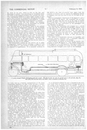
In a more luxurious type of combined system, also man& factured, the special large-capacity heating unit is equipped with a pressu:e fan. In this 'case the air is delivered throegh ducts down the whole length of the coach body, suitable air-outlet openings being arranged at a low level along the sides, and staggered. This unit will give an output of 30,000 B.T.U.s per hour at a temperature differenee of 140 degrees F., and will deliver some 220 cubic ft. of air per minute into the coach body via the air ducting.
The actual location of the heater unit requires. careful consideration. On some modern chassis, where the engine is situated midway down the vehicle, a position near the front end of the chassis is usually suitable for the location of the unit, A duct for the admission of fresh air can be arranged to lead from the front end to the heater, with the main ducting carried along each side below the seats.'
On the more normal type of chassis it may be found that the. only available space for the unit will be near the rear end. In such a case an air-inlet duct will be taken from a point in the roof, down behind the rear seat and thence to the heater, the outlets being arranged to suit the seating.