


Engine Design Simplifies Machining
Page 74
If you've noticed an error in this article please click here to report it so we can fix it.
DATENT No. 737,490 (G. Ospelt,
Herrengasse 70, Vaduz, Liechtenstein), deals with the construction of two-stroke oil engines. The chief point of the patent is the general layout, the design _being such that machining is simplified.
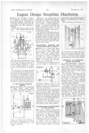
The drawing shows a section of the engine. The cylinder-block and the
upper part of the crankcase are in one piece, the chief feature of which is that its two sides are machined all over in divergent planes as shown at 1. Most of the external fittings are directly bolted on to this face or the opposite one.
On one side is the exhaust manifold (2) and the blower (3) whilst the other side carries the water-pump (4) and the oil cooler (5). The dynamo is located behind and in line with the water pump. The injection pump (6) and the starter (7) are secured to the cover-plate at the flywheel end. Belt drive is used for all the rotary accessories except the starter.
AN 01L-ENGINE STARTING DEVICE
FROM Rolls-Royce Ltd., Nightingale Road, Derby, comes patent No. 738.413, the subject of which is a device for aiding the starting of oi
engines. It works on the principle of introducing a small charge of volatile fuel into the induction pipe at the moment or starting.
B40 Referring to the drawing, the airintake pipe (1) is provided with a butterfly throttle (2) which can practically close the pipe. Attached to the side of the intake is a casing containing a packing of absorbent material and having connections above (3) and below (4) the butterfly valve. A perforated pipe (5) leads to the centre of the absorbent packing.
The pipe comes preferably from the dashboard of the vehicle where a fitting is located for the reception of a small pressurized capsule of ether. To start, the driver closes the throttle valve and at the same time pierces the capsule, so that for the first few strokes the engine receives ether vapour.
TRANSMISSION BRAKING FOR FOUR-WHEEL-DRIVE VEHICLE ATENT No. 738,295 (The Rover Co., Ltd., Meteor Works, Lode Lane, Coventry), deals with transmission brakes. On a vehicle having twoor four-wheel alternative drive, controlled by a clutch, it is preferable that when the transmission brake is applied, it shall operate on all ,four wheels, even though only two-wheel drive be in use at the time.
The -drawing shows diagrammatically how the scheme is worked out. 4
front-wheel propeller shaft (I) and another (2) for the rear wheels can be coupled or isolated by a dog-clutch (3) at the will of the driver.
The transmission brake is of the disc qpt, the disc (4) being mounted upon the rear propeller shaft. .The disc is hydraulically gripped by pistons (5) and the basis of the patent is that the dogclutch is also hydraulically operated by cylinder 6, so that braking must always occur through the four wheels.
Instead of the dog-clutch, a freewheel device can be used to couple the two propeller shafts during braking.
A RUBBER-SPRUNG ROAD-WHEEL BY ROLLS-ROYCE
T°prevent vibration arising in the road wheels from being transmitted to the hub, is the aim of a composite wheel shown in patent No. 737,587 (Rolls-Royce, Ltd., Nightingale Road, Derby). The wheel is built up from two members separated by rubber.
The drawing shows a half-section ol' the wheel. The rim carries an inwardly directed channel member (1) which embraces a flange (2) extending from the hub. The intervening space is filled by a channelled ring (3) made of rubber.
Before assembly, the hub flange is of the form shown in chain lines (4) so that it can be passed inside the rubber channel. Assembly is performed under a press, an . operation which expands the hub flange to its final large diameter, SIMPLICITY IN AUTOMATIC BRAKE ADJUSTERS:
A SELF-ADJUSTING mechanism 1-3for disc-type brakes is shown in patent "No. 738,247 (Wingfoot Corp., Akron, Ohio, U.S.A.). The scheine js ingenious in its simplicity and calls, for nothing mete than a return spring made from soft wire.
The operating mechanism is shown in the drawing: this comprises the splined disc (I) which can be gripped by spot-type friction pads (2 and 3). The brake is operated by applying hydraulic pressure to space 4 between the piston and the end plug, both of which are scaled by 0-rings.
The return spring (5) is the subject of the patent; it is made of soft steel , wire designed so that it has a limited recovery corresponding to the desired clearance, but any further compression will reduce it to a new and shorter working range. When it has become fully flattened, it can he re-stretched when new friction pads. are fitted.