


An Oil operated Automatic Clutch
Page 60
If you've noticed an error in this article please click here to report it so we can fix it.
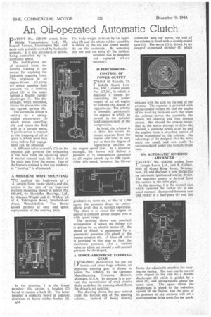
PATENT No. 628,499 comes from Hobbs Transmission, Ltd., 78, Russell Terrace, Leamington Spa, and deals with a clutch worked by hydraulic pressure. It is also automatic in action, being controlled by its rotational speed.
The clutch-plates are of standard form, the novelty residing in the means for applying the hydraulic engaging force, This originatzs in an engine-driven oil-pump (1) which supplies fluid pressure via a running gland (2) to the space behind a flexible rubber diaphragm (3,\ The diaphragm, when distended, forces the plates into contact against springs (4).
The automatic action is created by a spring loaded piston-valve (5) Which moves centrifugally and opens the fluid path at a certain speed. A gentle action is ensured tiy the trapping of oil in space 6; which must leak away. before :full engage
nient can be obtained. ._
:A differentvalve assembly (7) on the opposite side governs the• exhausting of the fluid from the operating space. A master control cock (8) is fitted in the main pipe from the pump. One of the features claimed ia that any tendency
to " hunting " is eliminated. .
RESILIENT BODY MOUNTING cushion the bodywork of a
vehkie from frame shocis and distortion ". is ihe aim of an improved resilient mounting shownin patent No. 628,668, by Harrisflex -Bearings, Ltd., H. Clayton-Wright and C. WiIday, all of 4, Tiddington Road, Stratford-onMon, WArwickshire. The device shown permits of easy and quick replacement of the wearing parts.
In the drawing, 1 is the frame member; this carries a bracket (2) bored to receive a bush (3). The latter member is conically bored in opposite directions to house rubber bushes (4).
A34
The body weight is taken by an upper plug (5) and the whole rubber assemblyis united by the nut and coned washer (6) on the underside., By removing this nut and the bolts (7) the resilient members can be detached and replaced when necessary.
SUPERCHARGER, CONTROL OF POWER OUTPUT E'ROM H. Ricardo, 21,
Suffolk Street, London, S.W.I, comes patent No. 627,361, in which is disclosed a means for controlling the power output of an oil engine by limiting the degree of supercharge. The scheme is intended particularly for engines in which an air-cell in the cylinder head receives most of the compression.
In brief, the scheme is to drive the blower by means separate from the engine and limit its output so that the degree of supercharge declines as the engine speed rises. In a practical example, the blower will deliver a pressure of 1 atmospheres (absolute) at all engine speeds up to 600 r.p.m. After this speed, however, the blower
produce:s no More air, so that at 1,500 r.p.m. the pressure drops to atmospheric level, that is, normal aspiration. The effect is to cause the engine to deliver a constant power output over, a wide speed range.
The drawing shows one practical arrangement in which the blower (I) is driven by an electric motor (2), the speed of which is maintained by a pneumatic governor (3) piped to the output conduit (4). A blow-off valve: is provided in this pipe to limit the maximum pressure, also a suction valve to admit air should a sub-normal pressure be developed.
A SHOCK-ABSORBENT STEERING GEAR
n,ESIGNED particularly for use on 1--; lorries and other large vehicles, an improved steeling gear is shown in patent No. 628,676, by the Gemmer Manufacturing Company, Detroit, Michigan, U.S.A. Its purpose is to-prevent the transmission of road shocks likely to deflect the steering wheel from the driver's set position.
The drawing shows the gear viewed from the bottom end of the steering column. Instead of being directly
connected with the worm, the end of the column is fitted with a doublg-ended cam (1). The worm (2) is driven by an integral segmented member (3) which•
engages with the cam on the end of the column. The segment is provided wieli spring-loaded rollers (4) and the angles of the working faces are such that when the column moves the assembly, the rollers are inactive and free motion occurs. But should the reverse occur, that is, the worm attempt to drive the column, a jamming action is set up and the applied force is absorbed instead of being transmitted to the column. An advantage of the design is that the extra parts are small, and can easily he accommodated under the bottom thrust race.
AN AUTOMATIC IGNITION ADVANCER
DATENT No. 628,206, comes from I, 'Joseph Lucas, Ltd., and B. Gilbert, both of Great King Street, Birmingham, 19, and discloses a new design for an automatic ignition-advancing device. The Opera tire power is derived from
the suction in the inlet pipe. .
In the drawing, 1 is the normal cam which operates the rocker (2) in the usual manner. Interposed between cam and rocker is a heel-piece ()) and this forms the adjustable member for varying the timing. The heel can be moved with respect to the cant by a flexible diaphragm (4) which is guided by a stem (5), and spring-loaded about the same stem. The space above the diaphragm is piped to the induction system of the engine, and the state of its pressure at any moment will set a corresponding firing point for the spark.