


MAKING BEST USE
Page 52
Page 53
Page 54
If you've noticed an error in this article please click here to report it so we can fix it.
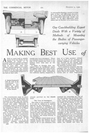
the Low LOADING-LINE ABUS or coach body is usually about twice the width of the chassis on which it is mounted, therefore special provision must be made to support the overhang on each side. The most common method employed is to make the cross-bearers of the bottom" framework of the body rigid enough to carry a considerable proportion of the load at their ends.
The cross-bearers must be about 3 ins, deep, because an allowance has to be made for the joints which are necessary in order that the bottom, side and other longitudinals may be framed into them. Moreover, a reasonable width of woodwork must be available throughout the length of the cross-bearer if it is to be flitchplated in a satisfactory manner.
The substance of the cross-bearer may be reduced by about one-third if an all-metal form of construction be adopted. But any real improvement in the design of the bottom framework is impossible if the foundation on which it is to be mounted remains comparatively narrow. For this reason many B34 chassis now have outriggers. These are brackets which are bolted to the • side of the chassis and have a top surface level with' that of the chassis.
It might be thought that outriggers were ati insufficient means for support unless they were accompanied by outer side frame members connecting their extremities. But sufficient rigidity, lengthwise, is
already provided by the chassis itself.
The Uses of Outriggers.
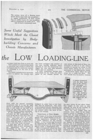
The value of the outrigger is that, if it can be bolted in a position selected by the bodybuilder, it can then be utilized to strengthen the lower corners of the main transverse units of the body framework. That is to say, the outrigger should be placed so that lower corner brackets at the foot of the side pillars may be extended and bolted directly to the outriggers.
The outrigger which forms an extension of the top surface of the chassis allows the bottom framework to be of less substance than
that or a body mounted without them—in fact, if the brackets be suitably designed, the floor may be laid directly on the chassis with only a layer of felt or other insulating material between them.
It is considered, however, that the outrigger may be further improved if it has an upper bearing surface below that of the chassis. Then any bottom side or other longitudinal required for connecting the feet of the side pillars may be turned edgewise, with the advantage that a better surface may be provided for the joints of the pillars, or for any lug or flange of the brackets or plates used. Moreover, with a low outrigger the bottoms of the pillars of a body with the usual skirt panels may rest on these brackets.
A more recent development of the outrigger is the pattern which is designed as part of a cross-member of the chassis and not as a separate item bolted to it, which, if improperly fitted, may weaken the chassis. These special cross-members provided for mounting the body pass under the chassis and have an
outrigger built into them at each end.
This method of construction tends to distribute any strain to which the outriggers may be subjected, instead of localizing it at the web of the chassis.
The motor manufacturer naturally wishes to deliver the chassis corn
plete with its special mounting equipment, but it is not an easy matter to arrange each outrigger so that it will come at the foot of a pillar of any body which may be designed for the chassis concerned. . If the outriggers are not to be adjusted by the bodybuilder they must be Set out so that they will not obstruct the step well of a doorway. The front pair of outriggers must, therefore, be a sufficient distance from the dash to allow for at least a 2-ft. 6-in, front entrance.
A pair may also be placed conveniently close to each extremity of the wheel-arch, one or more (according to the length of the chassis) between the wheel-arcb and the front outrigger and another at the rear, leaving sufficient space between it and the wheel-arch outrigger for any rear side entrance which may be required.
A wide foundation having thus been made for the body, the other parts of the chassis should be designed In order that a low loadline may be preserved. The main cross-members should, therefore, not be arched, and gearbox covers should not project above the level of the top of the chassis.
Importance of Floor Height.
The height of the floor of the lower saloon of a double-decker is of particular importance, because it has a direct influence on the Overall height. A few inches may be saved by offsetting the main drive, so that the differential and its cover may be placed under a longitudinal seat.
This arrangement allows the floor of the central gangway to be sunk below the floor under the seats. The only defect of this style of floor construction is that it is not always possible to conceal the whole of the cover which allows for the vertical movement of the differential casing.
Front-wheel drive offers the best scope for a really low floor. The rear wheels may be smaller, because the gear ratios do not affect them. The height of the axle is also reduced, as well as the arching of the frame over the back axle.
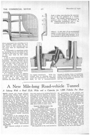
How the floor height may be reduced, when there is no transmission system to consider, is to be seen with the rear platform of a double-decker, which is mounted on the cranked tail ends of the chassis. Here, again, a wide base is required.
Usually the side overhang beyond the chassis is supported on crossbearers, but it is considered that a system of outriggers such as already described would be an advantage. The near-side overhang, as represented by the step or platform, has to withstand considerable strains when passengers are crowding on to • the platform, apart from the fact that three or four persons may at the same time be negotiating the staircase.
-A compromise is sometimes made by spreading out the tail ends of the chassis so that they are wider apart at the rear than at the crank position.
A bus or coach body should have a certain amount of flexibility in its mounting. The body should not be held down at more than five places on each side, even in the case of a large vehicle. The insertion of a rubber pad at the point of fixing will often prove advantageous, because it will give more allowance for the flexing of the chassis, without injury to the structure of the body.
If a certain amount of relative movement, however small, be allowed at each side of the body, there should be no rigid connection between the front of the body and the engine dashboard. With the normal type of steering this will entail the construction of a floating dash, Or for a forward-control chassis a similar form of mounting, either between the cab and the main portion of the body, or between the cab and its dashboard,