


Patents Completed.
Page 40
If you've noticed an error in this article please click here to report it so we can fix it.
Complete specifications of the following patents will be sent to any address in the United Kingdom upon receipt of eightpence per copy at the Sale Branch, Patent Office, Holborn, W.C.
SPEED GEAR.—t raig.—No. 17,434, dated 27th July, 1909.—This invention relates to variable-speed gears, and has
for its object to reduce the length of the shafts carrying the sliding gearwheels to a minimum. The driving shaft carries one set of sliding gearwheels, and one of the counterehafts carries two separate sliding gears, the idle one of which is adapted to be slid out of the way when the sliding gears on the driven shaft are changed from one position to another. With this arrangement, a considerable reduction in the length of the shafts carrying the sliding gears is obtained.
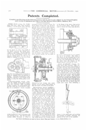
VARIABLE-SPEED GEAR. — Hennod—No. 22,462, dated, under Convention, 15th February, 1908.—According to this invention, the change-speed gear and the clutch are constituted by a number of suu-and-planet wheels -mounted
within the flywheel and co-operating with two braking drums. The driving shaft carries a hollow flywheel, in which is
mounted a number of planet wheels. The driven shaft extends into the flywheel. and its end is carried in ball bearings. Rigidly connected to the driven shaft is a suit wheel that permanently engages one set of planet wheels and through which the drive is transmitted to the driven shaft. Concentric with the driven shaft and surrounding the latter, are two sleeves, each of which carries a sun wheel at one end and a braking drum at the ether. The two SIM wheels mesh with their respective planet wheels, which are carried by a spindle common to both. The sleeve directly surrounding the driven shaft is slidable on the latter, and has a SUeunil sun wheel that is adapted to he slid into mesh with the set of planet wheels, for the purpose of reversing the direction of the drive. suitable brakes are provided for braking either of the drums or both together, so that either set of suit-and-planet gears may be locked, thus giving a range of three forward speeds; the top speed is obtained by both drums, and, consequently, all the gears, being locked, so that the whole will rotate as one piece.
DETACRA111.F. ROAD WHEELS.Wright.—No. 27,938, dated 23rd December, 1908.—The object of this invention is to render the road wheels of vehicles readily detachable. The hub of the wheel is mounted in ball bearings on the axle, and is externally screw-threaded. A cap is screwed on to the screwthreaded portion of the hub, and is formed, partly along its exterior, with a square thread of substantial pitch. Surrounding the cap is a flanged sleeve, which is provided with an internal square thread which engages the square thread on the cap. This flanged sleeve carries the nave of the wheel, which is bolted thereto. The cap is also formed with a number of external teeth, and a pa-vel is mounted on the nave of the wheel, and is adapted to be brought into engagement with the teeth on the cap for the purpose of locking the wheel in position. Drive is effected by means of a number of studs provided in the hub which project into recesses formed in the flange of the sleeve, that carries the nave of the wheel. When it is desired to detach the wheel from the huh, the pawl is disengaged so as to permit the cap to be rotated. The wheel is then drawn off the threaded part of the cap by screwing the latter further on to the hub, thus disengaging the studs on the latter from the recesses in the flanged member carrying the wheel.
GEAR QUADRANT.—Cusack.— No. 4,160, dated 19th February, 1909.—According to this invention, the quadrant is provided with the usual locking recesses which are adapted to be engaged by the locking bolt carried by the change-speed lever. The top of the slot in the quadrant is formed with a series of alternative concave and convex surfaces along which the bolt travels. This undulating surface is arranged so that its convex portions are opposite each locking recess formed in the lower edge of the quadrant. It will be seen that, in moving the hand lever, the bolt will be drawn down towards each recess, thus indicating a change in the speed ratio and avoiding the necessity of closely observing the position of the bolt on the quadrant.