


Novel Design for a Light Tractor
Page 48
If you've noticed an error in this article please click here to report it so we can fix it.
A Résumé of Patent Specifications that have Recently been Published. Copies May be Obtained From the Patent ORe. Price 11Each
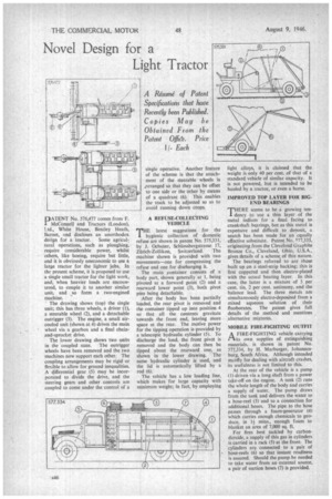
FIOATENT No. 576,477 comes from F. McConnell and Tractors (London), Ltd., White House, Bentley Heath, Barnet, and discloses an unorthodox degign for a tractor. Some agricul; tural operations, such as ploughing, require considerable power, whilst others, like hoeing, require but little, and it is obviously uneconomic to use a large tractor for the lighter jobs. In the present scheme, it is proposed to use a single small tractor fox the light work, and, when heavier loads are encountered, to couple it to another similar unit, and so form a two-engined machine.
The drawing shows (top) the single unit; this has three wheels, a driver (I), a steerable wheel (2), and a detachable outrigger (3). The engine, a small aircooled unit (shown at 4) drives the main wheel via a gearbox and a final chainand-sprocket drive.
The lower drawing shows two units in the coupled state. The outrigger wheels have been removed and the two machines now support each other. The coupling arrangements may be rigid or flexible to allow for ground inequalities. A differential gear (5) may be incorporated to divide the drive, and the steering gears and other controls are coupled to come under the control of a
single operative. Another feature of the scheme is that the attachment of the steerable wheels is zit-ranged so that they can be offset to one side or the other by means of a quadrant (6). This enables the track to be adjusted so as to avoid running down crops.
A REFUSE-COLLECTING VEHICLE THE latest suggestions for the hygienic collection of domestic refuse are shown in patent No. 575,331, by J. Ochsner, Schlossbergstrasse 17, Zilrich-Zoilikon, Switzerland. The machine shown is provided with two movements—one for compressing the refuse and one for discharging it.
The main ;container consists of a body part, shown generally at 1, being pivoted at a forward point (2) and a rearward lower point (3), both pivot pins being detachable.
After the body has been partially loaded, the rear pivot is removed and the container tipped up into position 4 so that all the contents gravitate towards the front end, leaving more space at the rear. The motive power for the tipping operation is provided by a telescopic hydraulic cylinder (5). To discharge the load, the front pivot is removed and the body can then be tipped about the rearward one, as shown in the lower drawing. The same hydraulic cylinder is used, and the lid is automatically lifted by a rod (6).
The vehicle has a low loading line, which makes for large capacity with minimum weight; in fact, by employing light alloys, it is claimed that the weight is only 40 per cent, of that of a standard vehicle of similar capacity. It is not powered, but is intended to be hauled by a tractor, or even a horse.
IMPROVED TOP LAYER FOR BIGEND BEARINGS
THERE seems to be a growing ten1 dency to use a thin layer of the metal indium for a final facing to crankshaft bearings, but as this metal is expensive and difficult to deposit, a search has been made for an equally effective substitute. Patent No. 577,335, originating from the Cleveland Graphite Bronze Co., Cleveland, Ohio, U.S.A., gives details of a scheme of this nature.
The bearings referred to are those built up on a steel-strip backing; this is first coppered and then electro-plated with the actual bearing layer. In this case, the latter is a mixture of 5 per cent. tin, 2 per cent. antimony, and the balance lead. The three metals are simultaneously electro-deposited from a mixed aqueous solution of their fiuoborates. The patent gives full details of the method and mentions alternative mixtures.
MOBILE FIRE-FIGHTING OUTFIT
A FIRE-FIGHTING vehicle carrying (tits own supplies of extinguishing materials, is shown in patent No. 577,334, by H. Marburger, Johannesburg, South Africa. Although intended mairtly for dealing with aircraft crashes, its usefulness is not limited to this.
At the rear of the vehicle is a pump (1) driven via a long shaft from a power take-off on the engine. A tank (2) runs the whole length of the body and carries a supply of water. The pump draws from the tank and delivers the water to a hose-reel (3) and to a connection for additional hoses. The pipe to the hose passes through a foam-generator (4) which carries enough chemicals to produce, in 14 mins., enough foam to blanket an area of 7,000 sq. ft.
For fires best tackled by carbondioxide, a supply of this gas in cylinders is carried in a rack (5) at the front. The cylinders are connected to a pair of hose-reels (6) so that instant readiness is assured. Should the pump be needed to take water from an external source, a pair of suction hoses (7) is provided.