


SENTINEL INTF DUCES AN 01L-ENC [ED 7-8-TONNER
Page 34
Page 35
Page 36
If you've noticed an error in this article please click here to report it so we can fix it.
et rot Engine Offered in New h the Power Unit is Mounted Frame Behind the Cab
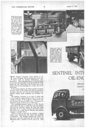
THE Sentinel 7-8-tonners which figured in the recent Cavalcade were the prototypes of two new chassis built by Sentinel (Shrewsbury), Ltd.. Shrewsbury. The outstanding feature of Sentinel design is, of course, that the engine is located beneath the frame behind the cab, which leaves the forward end of the chassis clear for the mounting of a roomy cab free of
obstruction. .
In the present instance, the fullest possible advantage has been taken of this feature, not only to provide an extremely capacious cab, but one that embraces comfortable seating, ample ventilation and excellent visibility.
The Sentinel 7-8-tonner, as an oiler, is fitted with a four-cylindered engine having a bore of 4; ins, and a stroke of 5:1 ins. It has an R.A.C. rating of 36.1 h.p. and develops 90 b.h.p. at 2,000 r.p.m. It produces its maximum torque of 255 ft.-lb. at 1,500 r.p.m.
The combustion-chamber system is of the Ricardo Comet Mark III type, in which the swirl cell contains only half the clearance volume, the other half being accounted for by a cavity formed in the piston crown. The system has a high thermal efficiency and pressure charging is possible with it.
There is a head to each pair of cylinders, a feature which assists maintenance and reduces the possibility of distortion. The camshaft operates the valves via cam levers and short push-rods, the valve gear being lubricated under a pressure of 10 lb. per sq. in. Each cylinder head is fitted with a quickly detachable aluminium cover, the removal of which provides access for inspection and adjustment
Cast iron is used for the one-piece crankcase and cylinder block, in which the maximum degree of rigidity has been attained The block is fitted with austenitic cast-iron liners, and the five cast-iron main-bearing caps, which are held by nickel-chrome-steel studs, are of substantial proportions. Ready access to the crankshaft and main bearings can be gained by the removal of an aluminium cover bolted to the cylinder-block casting.
The crankshaft, which is made from a cast-iron alloy, has 3i-in. diameter journals and 3-in, diameter crankpins. It is carried in five lead-bronze steel-strip bearings, and these, and the big-end bearings, which are of a similar type, are lubricated under a pressure of 60 lb. per sq. in. Nickel-chrome-steel stampings are used for the connecting rods, the big-end caps of which are held by four bolts: phosphor-bronze bushes are employed for the small ends. There are five rings on each aluminium alloy piston—three pressure rings and a slotted scraper ring above the gudgeon pin, and a second slotted scraper ring below.
Camshaft drive is by spur gears and duplex chain from the crankshaft, the fuel pump and water pump being driven by bevel gearing direct from the crankshaft. The whole assembly is encased with an aluminium cover which carries the fuel pump and water pump, the former being of C.A.V. make and
provided with a centrifugal governor. The fuel nozzles are of the pintIe type, the spray angle being 12 degrees.
The petrol unit is offered as an alternative, this being a four-cylindered engine of the same bore and stroke as the oil engine, and having a torque of 260 ft.-lb at 1,600 r.p.m. Some of the features of this engine are that it has pressed-in renewable dry-type cylinder liners, push-rod-operated overhead valves, and downdraught carburetter. Ignition is by coil, and it is noteworthy that the distributor head is brought out well clear of the engine, which not only protects it from road matter, but renders it remarkably accessible.
Overdrive Top Gear
In the case of the oil-engined chassis, a five-speed-andreverse gearbox is used, the fifth speed being an overdrive ratio, the respective road speeds, with 36-in. by 8-in. tyres, a 6.75 to 1 rear axle ratio, and the engine running at 2,000 r.p.m., being 5.45, 10.2, 18.4, 33.1 and 44.1 m.p.h.
The petrol-engined chassis has a four-speed-andreverse gearbox which, with similar tyre equipment, a rear axle of the same ratio and an engine speed of 2,400 r.p.m., gives the following road speeds in m.p.h.: first, 6.58; second, 12.2; third, 21.157 and fourth, 40. A 14-in, single-plate dry clutch is used, and from the gearbox a short open-type shaft, with needle-roller universal joints, takes the drive to the rear axle, which has overhead-worm gear. The drive shafts are, of course, fully floating, and the one-piece axle casing, made in alloy steel, is characteristic of the general solidity which is evident in every chassis detail.
Taking Up Shackle Play The semi-elliptic springs are 3i ins, wide, those at the front having 48-in, centres and those at the rear 54-in. centres. The shackles incorporate means for taking up any side play which may develop. Disc-ty,pe wheels are used, being secured by 10 studs. As previously mentioned, the tvres fitted as standard have dimensions of 36 ins. by 8 ins., whilst there are twins at the rear.
Braking is on the Lockheed hydraulic system with servo assistance for the foot brake, which operates on all four wheels. The hand brake, as is usual, takes effect only on the rear wheels.
Cam and double-roller-type steering gear is employed, in conjunction with a spring steering wheel of large diameter. The steering-gear joints, incidentally, are self-adjusting.
In view of, the position of the engine, special arrangements have to be made for hand cranking, and this is carried out by running a universally jointed shaft forward from the unit to the front end. Here it is jointed to another shaft carried in the base of a casting whicti forms the mounting for the dynamo and four-bladed fan, which are driven in tandem by a duplex chain running in an oil-tight casing.
An Impressive Front
The flexibly mounted radiator block is covered in by a readily removable plated-frame grille, and this, in conjunction with the sunk headlamps, two-piece windscreen, and tumble-home of the cab sides, gives a most imposing frontal aspect Filler caps on the radiator and fuel tank are of the spring-loaded, wedge-operated type, and can be removed or secured by a simple half-turn movement.
Lighting and starting equipment on both models operates on 24 volts, the batteries being located under the cab seats in separate compartments.
Of all-steel construction the cab is flexibly mounted on the frame. Some of its special features include sliding doors, roof ventilation, two-piece windscreen, in which the driver's section opens and comfortably upholstered full-length sectional driving seat and back rest. The chief virtues of the sliding doors are that the vehicle can be parked without consideration for the normal clearance required by a hinged door, and, further, they add to safety on the road.
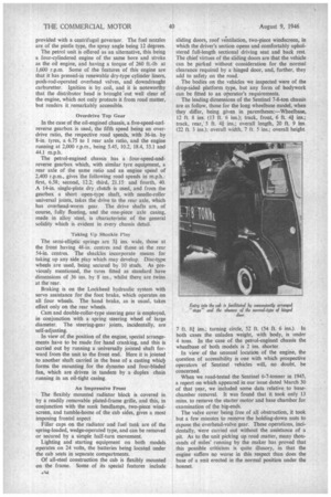
The bodies on the vehicles we inspected were of the drop-sided platform type, but any form of bodywork can be fitted to an operator's requirements.
The leading dimensions of the Sentinel 7-8-ton chassis are as follow, those for the long wheelbase model, when they differ, being given in parentheses:—Wheelbase, 12 ft. 8 ins. (13 ft. 6 ins.); track, front, 6 ft. 41 ins.; track, rear,' 5 ft. 41. ins.; overall length, 20 ft. 9 ins. (22 ft. 3 ins.); overall width, 7 ft. 5 ins.; overall height.
7 ft. 81 ins.; turning circle, 52 ft. (54 ft. 6 ins.). In both cases the unladen weight, with body, is under 4 tons. In the case of the petrol-engined chassis the wheelbase of both models is 2 ins. shorter.
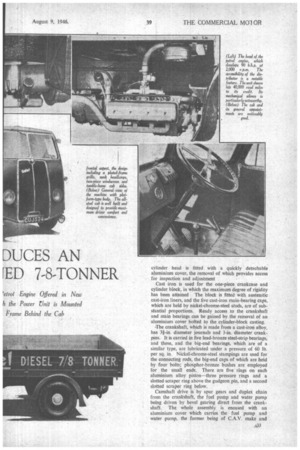
In view of the unusual location of the engine, the question of accessibility is one with which prospective operators of Sentinel vehicles will, no doubt, be concerned.
When we road-tested the Sentinel 6-7-tonner in 1945, a report on which appeared in our issue dated March 30 of that year, we included some data relative, to basechamber removal. It was found that it took only 13 mins. to remove the starter motor and base chamber for examination of the big-ends.
The valve cover being free of all obstruction, it took but a few minutes to remove the holding-down nuts to expose the overhead-valve gear. These operations, incidentally, were carried out without the assistance of a pit. As to the unit picking up road matter, many thousands of miles' running by the maker has proved that this possible criticism is quite illusory, in that the engine suffers no worse in this respect than does the base of a enit erected in the normal position under the bonnet.