


Oil-engine Practice in Spark-ignited Engines
Page 54
If you've noticed an error in this article please click here to report it so we can fix it.
COMBUSTION-CHAMBER improvementsments form the subject of patent No. 961,724 by S. A. Adolphe Saurer, Arbon, Switzerland. This invention provides another instance of the way in which oil-engine practice is responsible for further developments in the design of petrol units.
Referring to the accompanying drawing, it will be seen that the piston crown is hollowed to form a compres sion space for the gases. The shape is such that as the piston rises a rotary motion of the mixture is created, culminating in a vigorous swirl at topdead-centre. The advantage is stated to lie in the action of the swirl in assisting flame propagation, coupled with the thorough scavenging of the plug points. Whilst suitable for all mixture-using engines, the scheme is claimed to be of special advantage in conjunction with suction-gas plants.
An Automatic Mixture-enricher for Cold Engines.
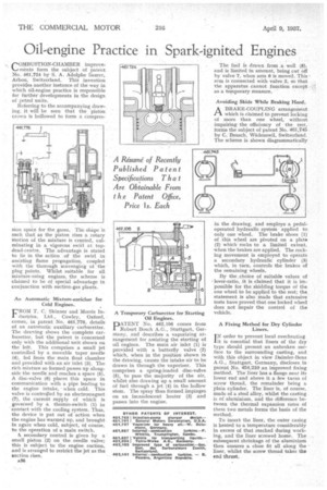
FROM T. C. Skinner and Morris Industries, Ltd., Cowley, Oxford, comes, in patent No. 461,776, details of an automatic auxiliary carburetter. The drawing shows the complete carburetter, but the patent is concerned only with the additional unit shown on the left. This comprises a small jet controlled by a movable taper needle (4), fed from the main float chamber and provided with an air inlet (3). The rich mixture so formed passes up alongside the needlel and reaches a space (5). A disc-valve (6) places this space in communication with a pipe leading to the engine intake, • when cold. This valve is controlled by an electromagnet (7), the current supply of which is governed by a therrno-switch (1) in contact with the cooling system. Thus, the device is put out of action when the engine has warmed up, and brought in again when cold, subject, of course, to the operation of a main switch.
A secondary control is given by a small piston (2) on the needle valve; this is subject to the engine suction, and is arranged to restrict the jet as the suction rises.
A36 A Temporary Carburetter for Starting Oil Engines.
PNo. 462,106 comes from Robert Bosch A.G., Stuttgart, Germany, and describes a vaporizing arrangement for assisting the starting of oil engines. The main air inlet (1) is provided with a butterfly valve (2) which, when in the position shown in the drawing, causes the intake air to be drawn in through the vaporizer. This comprises a spring-loaded disc-valve (5), to pass the majority of the air, whilst also drawing up a small amount of fuel through a jet (4) in the hollow stem. The spray thus formed impinges on an incandescent heater (3) and passes into the engine. The fuel is drawn from a well (8)-, and is limited in amount, being cut off by valve 7, when arm 6 is moved. This arm is connected with valve 2, so that the apparatus cannot function except as a temporary measure.
Avoiding Skids While Braking Hard.
ABRAKE-COVPLING arrangement which is claimed to prevent locking of more than one wheel, without impairing the efficiency of the rest, forms the subject of patent No. 461,745 by C. Beusch, Wadenswil, Switzerland. The scheme is shown diagrammatically
in the drawing, and employs a pedal.. operated hydraulic system applied to only one wheel. The brake shoes (I) of this wheel are pivoted on a plate (2) which rocks to a limited extent, when the brakes are applied. The rocking movement is employed to operate a secondary hydraulic cylinder (3) which, in turn, controls the brakes of the remaining wheels.
By the .choice of suitable values of lever-ratio, it is claimed that it is impossible for the skidding torque of the one wheel to be applied to the rest; the statement is also made that extensive tests have proved that one locked wheel does not impair the control of the vehicle.
A Fixing Method for Dry Cylinder Liners.
I N order to prevent local overheating it is essential that liners of the dry type should present an unbroken surface to the surrounding casting, and with this object in view Daimler-Benz A.G., Stuttgart, Germany, discloses in patent No. 454,210 an improved fixing method. The liner has a flange near its lower end • and above it a few turns of screw thread, the remainder being a plain cylinder. The liner is, of course. made of a steel alloy, whilst the casting is of aluminium, and the difference between the thermal expansion rates of these two metals forms the basis of the method.
To insert the liner, the outer casing is heated to a temperature considerably in excess of that reached during working, and the liner screwed home. The subsequent shrinkage of the aluminium then ensures a close fit all along the liner, whilst the screw thread takes the end thrust.