


The Davis Paraffin Carburetter.
Page 3
Page 4
If you've noticed an error in this article please click here to report it so we can fix it.
A Mechanically-operated Device with Precision Feed for the Liquid Fuel.
One of the interesting exhibits at the Olympia show was the Davis paraffin carburetter which was exhibited by the inventor, Mr. F. R. Davis, of Shawford, Winchester, and for which device Messrs. Rush and Aloof, of 199, Piccadilly, London, W., are the agents. A representative of "THE COMMERCIAL MOTOR " recently had a run on a 12h.p. car which was fitted with this form of carburetter and, although the conditions of traffic were totally unfavourable for any engine in the cylinders of which paraffin fuel was being consumed, the performance was very encouraging. It was noticed that the firing was, at times, rather irregular, but a subsequent examination of the plugs showed that one of them had a cracked porcelain, and that this had led to occasional " shorting " of the high-tension current.
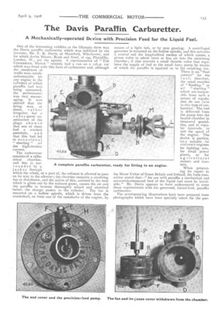
The carburetter consists of a cylindrical chamber, and this is surrounded by a jacket through which the whole, or a part of, the exhaust is allowed to pass on its way to the silencer ; the chamber contains a revolving fan or distributor, and the action of this, assisted by the heat which is given out by the exhaust gases, causes the air and the paraffin to become thoroughly mixed and atomised before the charge passes to the cylinder. The fan is mounted on a hollow spindle, which is driven from the crankshaft, or from one of the camshafts of the engine, by
means of a light belt, or by spur gearing. A centrifugal governor is mounted on the hollow spindle, and this actuates a central rod the longitudinal motion of which causes a piston valve to admit more or less air into the atomising chamber ; it also controls a small throttle valve that regulates the supply of fuel to the small force pump by means of which the paraffin is squirted on to the revolving fan. There is no "float control" for the I uel; therefore, the usual troubles of " flooding " or of " starving " which are inseparable from such a means of regulation do not exist in this type of carburetter. The fuel is delivered from the pump into the heated chamber in measured quantities, and at regular intervals, to suit the speed of the engine. The device is particulary suitable for stationary engines for lighting sets, for small power plants, or for agricultural motors and tractors.
When presenting its report to the Motor Union of Great Britain and Ireland, the fuels committee stated that—" for use with paraffin a mechanical and accurately-measured feed of the liquid fuel must be inevitable." Mr. Davis appears to have endeavoured to meet these requirements with his governed, forced-feed, paraffin carbtretter.
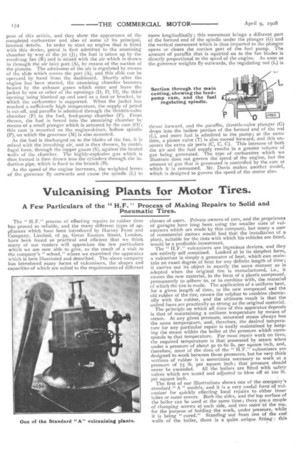
The accompanying illustrations have been prepared from photographs which have been specially taken for the put. pose of this article, and they show the appearance of the completed carburetter and also of some of its principal, internal details. In order to start an engine that is fitted with this device, petrol is first admitted to the atomising chamber by way of the jet (J) ; the fuel is taken up by the revolving fan (R) and is mixed with the air which is drawn in through the air inlet port (A), by reason of the suction of the pistons. The admission of the air is regulated by means of the slide which covers the port (A), and this slide can be operated by hand from the dashboard. Shortly after the engine has been started, the atomising chamber becomes heated by the exhaust gases which enter and leave the jacket by one or other of the openings (D, D, D), the third opening being blanked up and used as a foot or bracket, by which the carburetter is supported. When the jacket has reached a sufficiently high temperature, the supply of petrol is cut off, and paraffin is admitted through the throttle-valve chamber (F) to the fuel, feed-pump chamber (F). From thence, the fuel is forced into the atomising chamber by means of a small plunger which is actuated by the cam (0); this cam is mounted on the engine-driven, hollow spindle (P), on which the governor (M) is also mounted.
As the fuel is discharged on to the blades of the fan, it is mixed with the inrushing air, and is then thrown, by centrifugal force, through the copper gauze (S), against the heated walls of the chamber. The highly-explosive gas which is thus formed is then drawn into the cylinders through the induction pipe, which is fixed to the branch (B).
As the speed of the engine increases, the weighted levers of the governor fly outwards and cause the spindle (L) to move longitudinally; this movement brings a different part of the formed end of the spindle under the plunger (G) and the vertical movement which is thus imparted to the plunger opens or closes the suction port of the fuel pump. The amount of paraffin that is squirted on to the fan blades is directly proportional to the speed of the engine. As soon as the governor weights fly outwards, the regulating rod (L) is thrust forward, and the paraffin, throttle-valve plunger (G) drops into the hollow portion of the formed end of the rod (L), and more fuel is admitted to the pump; at the same time, a piston valve (T) is also moved forward, and this uncovers the extra air ports (C, C, C). This increase of both the air and the fuel supply results in a greater volume of gas being generated. The type of carburetter which we illustrate does not govern the speed of the engine, but the amount of gas that is generated is controlled by the rate at which it is consumed. Mr. Davis makes another model, which is designed to govern the speed of the motor also.