 1
1 2
2 3
3 4
4 5
5 6
6 7
7 8
8 9
9 10
10 11
11 12
12 13
13 14
14 15
15 16
16 17
17 18
18 19
19 20
20 21
21 22
22 23
23 24
24 25
25 26
26 27
27 28
28 29
29 30
30 31
31 32
32 33
33 34
34 35
35 36
36 37
37 38
38 39
39 40
40 41
41 42
42 43
43 44
44 45
45 46
46 47
47 48
48 49
49 50
50 51
51 52
52 53
53 54
54 55
55 56
56 57
57 58
58 59
59 60
60 61
61 62
62 63
63 64
64 65
65 66
66 67
67 68
68 69
69 70
70 71
71 72
72 73
73 74
74 75
75 76
76 77
77 78
78 79
79 80
80 81
81 82
82 83
83 84
84 85
85 86
86 87
87 88
88 89
89 90
90 91
91 92
92 93
93 94
94 95
95 96
96 97
97 98
98 99
99 100
100 101
101 102
102 103
103 104
104 105
105 106
106 107
107 108
108 109
109 110
110 111
111 112
112 113
113 114
114 115
115 116
116 117
117 118
118 119
119 120
120 121
121 122
122 123
123 124
124 125
125 126
126 127
127 128
128 129
129 130
130 131
131 132
132 133
133 134
134 135
135 136
136 137
137 138
138 139
139 140
140 141
141 142
142 143
143 144
144 145
145 146
146 147
147 148
148 149
149 150
150 151
151 152
152 153
153 154
154 155
155 156
156 157
157 158
158 159
159 160
160 161
161 162
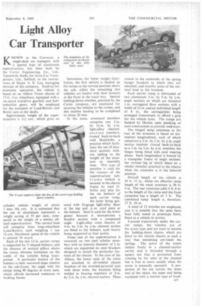
162 Light Alloy Car Transporter
Page 105
If you've noticed an error in this article please click here to report it so we can fix it.
KNOWN as the Carveyor, a single-deck car transport, with a special type . of aluminium superstructure, has been built by the Carter Engineering. Co., Ltd.. Tarnworth, Staffs, for Avon Car Transporters. Ltd., Solihull, to the instructions of Major A. E. Lea, managing director of this company. Evolved for economic operation, the vehicle is based on an Albion Victor chassis of 17-ft, 3-in, wheelbase, equipped with a six-speed overdrive gearbox and hubreduction gears, will be employed for the transport of Land-Rovers and Rover cars to the docks.
Approximate weight of the superstructure is 111 cwt., which gives an unladen vehicle weight of about 3 tons 18-1 cwt. It is estimated that the use of aluminium represents a weight saving of 55 per cent., compared to the weight of a similar allsteel superstructure. The normal load will comprise three long-wheelbase Land-Rovers, each weighing 1 ton 12 cwt. Maximum speed of the vehicle is around 56 m.p.h.
Each of the two 12-in, carrier ramps is supported by V-shaped bolsters, and the absence of vertical pillars above the ramps obviates limitation on the width of the vehicles being transported. A particular feature of the bolsters is their rearward slope relative to the sub-frame, the angle with the ramps being 90 degrees in every ease, which affords increased resistance to braking forces. Sometimes, for better weight distribution, the first vehicle is backed up the ramps to the normal position above the cab, whilst the remaining two vehicles are loaded with their bonnets at the front in the usual way. Special holding-down winches, patented by the Carter company, ,arc employed for securing the vehicles to the ramps, and this enables loading to be completed in about 20 min.
In 'the main, structural members comprise two 3-in. by 11-in. by *-in. light-alloy channelsection members. riveted back-to-back with Huckbolts, a practice which facilitates the use of standard sections without adding to the weight of the structure or aSsembly time. This type. of member is used for the runners of the superstructure subframe (which is secured to the chassis frame by steel Ubolts) and also for the six bolsters of each carrier ramp, the latter being gusseted with 10-gauge light-alloy sheet at the top and steel plate at the bottom. Steel is used for the lower gusset because it incorporates a bracket section with a compound angle. Light-alloy cross bearers of 4-in. by 2-in. by +-in. channel section are fitted to the bolsters, each bearer being supported at four points.
Front end of the superstructure is mounted on two steel tubular members with an internal diameter of 2 in. which are supported on steel brackets designed to match the particular features of the chassisIn the case of the Albion, the lower ends of the tubes are attached to all-welded chassis brackets of the inverted-pyramid type with three webs, the brackets being welded to bracing members of 2-in. by 2-in. by +-in. channel section. These extend to the underside of the spring hanger brackets to which they are attached, and transfer some of the vertical load to the brackets.
Each carrier ramp is fabricated of two aluminium 3-in. by 3-in. by +-in. angle sections on which are mounted corrugated floor sections with a width of 12 in. and an individual length of 8 in., the corrugations being arranged transversely to afford a grip for the vehicle tyres. The ramps are flanked by Dexion open planking of steel construction to provide walkways.
The hinged ramp extension at the 'rear of the structure is based on aluminium longitudinals, each of which comprises a 3-in. by 3-in. by +-in. angle section member riveted back-to-back to a 2-in. by 2-in. by +-in. member, the hinges being fitted with steel wearing plates. Each longitudinal is braced by a triangular frame of angle sections, the vertical leg 'of which bears on a similar Member attached. to the chassis when the extension is in the lowered position.
Overall length of the .vehicle is 29 ft. 11 in., whilst the effective ramp length of the main structure is 30 ft. 4 in. The rear extension adds 4 ft. 6 in. to the length of the ramp and the front extension has a length of 3 ft. The combined ramp length is, therefore, 37 ft. 10 in A total of 12 winches are employed, and it is notable that the units have been fully tested in prototype form, fitted to a vehicle in service.
Located transversely under the carrier ramps, the winches are of the screw type and are used to tension the holding-down chains, which are fitted to the vehicle chassis in such a way that tensioning pre-loads the springs. The screw of the winch rotates freely in a channel-section carrier and is threaded through a square nut that is prevented from rotating by the sides of the channel but is free to move axially when the screw is manually operated. A projection of the nut carries the inner end of the chain, the outer end being equipped with a normal type of hook.