


A Double-decker with Front-wheel Drive
Page 62
If you've noticed an error in this article please click here to report it so we can fix it.
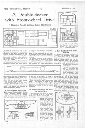
CERTAIN advantages, such as improved visibility, no working parts beneath the floor which carries the passengers, improved accessibility of engine, etc., and ease of removal of the power-unit, are claimed in the patent of the Gilford Motor Co., Ltd., and E. B. Horne, No. 353,902.
As will be seen from the accompanying drawing, the engine (2) is mounted immediately behind the front axle, a
shaft leading from it to the gearbox (3) and a short shaft leading back to the differential gear, from which two cardan shafts (6) lead to the front wheels, which are the driving wheels.
The driver's seat is in the space marked 7, from which he should get an exceptionally good view of the road in front. The wheels are described as being independently sprung.
A Brake-testing Apparatus.
THE name of Tecalemit, Ltd., Scrubbs • Lane, Willesden, London, N.W.10, appears in specification No 354,109, which describes a brake-testing apparatus. The vehicle to be tested is driven up ramps so that its front wheels rest on what are described as chariots, whilst its rear wheels rest on two similar chariots, all four of them being provided with wheels which rest on sloping surfaces.
A cable is connected to the vehicle so that it is pulled up the slopes by means of a piston working in a cylinder into which compressed air is introduced. The lefficiency of a brake is determined by the fact of the wheel, to which it is attached, revolving instead of carrying the chariot up the slope. Four chariots are used, one to each wheel. No mention is made of the testing of six-wheeled vehicles, which presents a more dillcult problem where each of the wheels is to be tested separately.
An Adjustable Means for Heating the Mixture.
THE induction pipe shown in patent
No. 353,714, by G. R. Welch, 746, Collingwood Avenue, Detroit, U.S.A., is so arranged that a wall (D) in the exhaust pipe forms a chamber in which the square tube (C) can rotate in the pivot (G) for the purpose of regulating the heat to be imparted to the mixture as it passes to the induction pipe.
The right hand lower view shows the vertical passage leading from the carburetter and the mixture passing through C to the wall (D), where it is heated. The upper view shows the
A New Bendix-Perrot Brake Feature.
IN patent No. 354,038, Bendix-Perrot Brakes, Ltd., Westwood Road, Wilton, Birmingham, and H. Clark refer to a means for centralizing the two shoes of a brake, should one wear unevenly with the other. The arrangement applies particularly to that class of brake in which a turnbuckle is em ployed for the adjustment of the shoes.
A stud (A) is provided with a substantial nut • and.flats, so that it can • be held while the nut is being tightened. T h e • hole in the back plate
• through which it passes is in the form of ft slot, so that when the nut is slackened and the brake applied the stud (A) is free to take up a position which will ensure that the two shoes find a central Position. The nut then being tightened allows the turnbuckle to be rotated by means of the gear (G), which is integral with the right-hand and left-band screwed parts.
The spring (E) holds the ends of the shoes against the turnbuckle ends, permitting an equalized servo action.