


A NEW FRICTION GEARING.
Page 30
If you've noticed an error in this article please click here to report it so we can fix it.
A Résumé of Recently Published Patent Specifications.
QLITE a revolutionary method of driving by means of friction is describeAl in specification No. 237,743, Charles R. Garrard. Some time back we described the same invention applied to the driving of shafts which
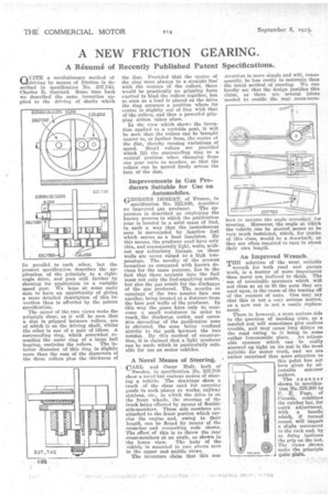
lie parallel to each other, but the present specification describes the application of the principle . to a rightangle drive, and goes still farther by showing its application to a variable speed gear. We hope at some early date to have an opportunity of giving a more detailed description of this invention than is afforded by the patent specification.
The upper of the two views make the principle clear, as it will be seen that a disc is gripped between rollers, one of which is on the driving shaft, whilst the other is one of a pair of idlers. A surrounding ring, which somewhat resembles the outer ring of a large ball bearing, encircles the rollers. The inteller diameter of this ring is slightly more than the sum of the diameters of the three rollers plus the thickness of
the disc. Provided that the centre of the ring were always in a straight line' with the centres of the rollers, there would be practically no gripping force exerted to bind the rollers together, but so soon as a load is placed on the drive the ring assumes a position where its centre is slightly out of line with that of the rollers, and then a powerful gripping action takes place.
In the view which show:, the invention applied to a variable gear, it will be seen that the rollers can be brought nearer to, or farther from, the centre of the disc, thereby causing variations of speed. Small rollers are provided which lift the surrounding ring to a central position when changing from one gear ratio to another, so that the rollers can be moved freely across the face of the disc.
Improvements in Gas Producers Suitable for Use on Automobiles.
GEORGES IMBERT, of France, in
specification No. 222,549, describes an improved gas producer. The apparatus is described as employing the known process in which the gInsification zone is located in a solid mass of fuel, in such a way that the incandescent zone is surrounded by inactive fuel which serves as a heat insulator. By this means, the producer need have only thin, and consequently light, walls, without any refractory linings, as these walls are never, raised to a high temperature. The novelty of the present invention as compared with known devices for the same purpose, lies in the fact that there projects into the fuel mass not only the fuel-supplying nozzle, but also the gas nozzle for the discharge of the gas produced. The mouths or openings of the two nozzles face one another, being located at a distance from the base and walls of the producer. In this way the gases have only to overcome a small resistance in order to reach, the discharge outlet, and excessive spreading of the gasification zone is obviated, the zone being confined strictly to the path between the two nozzles. By this method of construction, it is claimed that a light producer can be made which is particularly suitable for use on motor vehicles.
A Novel Means of Steering. v CARL and Oscar Unit, both of Sweden, in specification No. 237,789 show a nevel but curious means of steering a vehicle. The • drawings show a truck of the class used for carrying goods in such places as works, railway stations, etc., in which the drive is on the front wheels, the steering of the truck being effected by means of flexible side-members. These side members are attached to the front portion which carries the engine and, mink to their length, can be flexed by means of the cross-bar and connectina° rods shown. The effect of this is to throw the rear cross-members at an angle, as shown in the lower view. The body of the vehicle is mounted in two pivots seen in the upper and middle views.
The inventors claim that this con
struction is more simple and will, consequently, be less costly to maintain than the tisual method of steering. We can hardly see that the design justifies this claim, as there are several joints needed to enable the rear cross-mem bers to assume the angle necessary for steering. Moreover, the angle at which the 'vehicle .can be steered seems to be very much restricted, which, for trucks of this class, would be a drawback, as they are often required to turn in about
their own -length. .
An Improved Wrench. •
1 selection of the most suitable
wrench for both road and garage work, is a matter of more importance than many are inclined to think. The use of unsuitable. spanners which will not close so as to fit the nuts they are used upon, is the cause of the tearing off of the corners of nuts. One may, say that this is not a very serious Matter, as a new nut is not a costly , replace
ment. .
There is, however, a more serious side to the question of mauling nuts, as a mauled nut will sometimes give endless trouble, and may cause long delays on the road owing to it being in some rather inaccessible place. An adjustable spanner which can be really screwed up tight on its nut is the most suitable for motor work, and we are rather surprised that more attention tothis point has not been given by adjustable spanner makers.
The spanner shown in specification No. 226.205 by P. E, Page, of Canada, combines the ratchet bar, for quick adjustment, with a handle which, if turned round, will impart a slight movement to the rack and, by so doing increase the grip on the nut. The views shown make the principle quite plain.