


Sheet-metal Hydraulic-brake' Pistons
Page 36
If you've noticed an error in this article please click here to report it so we can fix it.
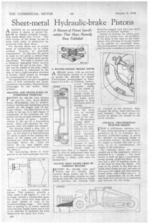
A Résumé of Patent Specifications That Have Recently Been Published ADESIGN for an hydrazine-brake piston is shown in patent No. 655,156 by Bendix Aviation Corpora
'lion, South Bend, Ind., U.S.A. The chief feature of the design is. that it lends itself easily to production by presswork from sheet metal. .
The drawing shows one of several forms of •construction, all of which conform, however, to presswork requirements. In this case the piston is made in wo parts, a dished body. (2) and a disc (1) which backs up. the cup-washer. The body is formed with a diametral depression which receives and locates the end of the shoe. The disc may be welded to the body, whilst the cup-washer is vulcanized to the disc, 'so that a rigid' one-piece structure is formed, which cannot be damaged by misplacement of the parts,
The specification also gives magnified views of both yulcanized and unvulcanized-on cup-washers, illustrating the advantages of the former under pressure.
HEATING AND VENTILATING OF PASSENGER VEHICLES
PATENT No. 555,124, from Thomas Ash and Co., Ltd., 10-14, Berkley Street, Birmingham, and E. Ludlow, shows a heating and ventilating system suitable for the largest type of passenger vehicle. The clief feature of the system is the use of a mild degree of compression of the circulated air; this 'permits the use of small Conduits, result
ing in economy of space. Another novelty is the use of a heat-storing device, which will maintain the temperature after the engine has stopped.
The drawing shows a plan view of an installation suitable for a single-deck bus. At the front is a heat-exchanger (1) which is piped in the cooling-water circuit of the engine and heats the incoming air, which then passes into a centrifugal blower (2). From the , blower the air, then slightly compressed; is discharged into the vehicle, via ducts 3.
The heat-storing device is incorporated in the heat-exchanger and con
sists of a tank containing sodium acetate. This chemical, normally a solid, melts at 58 degrees C., and, in so doing, absorbs a considerable quantity of heat, about four times that of an equal volume of water in the
normal-to-boiling, range. This latent heat of Melting is, of course, returned when the heat supply Ceases and is said to be sufficient to maintain the body temperature for about four hours.
4,34
-A WATER-COOLED BRAKE DRUM , ABRAKE drum, with an enclosed
water-jacket around it, is shown in 'patent No. 552,436, by Societe D'Inventions Aeronautiques et Meca niques S.I.A.M., of Fribourg, Switzer1 a n d. Althought, intended chiefly. for the wheels of aircraft, the scheme would be equally suitable for any brake drum subjected to long and heavy spells of heating. -.
It is proposed to form the drum with an internal water space (1)-. cored in the cast ' ing. The increased cooling effect is brought a b ou t, first, by the establishment of a circulatory system _which materially increases the area of radiation, and, secondly, on account of water _ having the highest known value of specific heat; that is,' it requires more heat to raise its temperature than does any other known substance. In case of boiling, a safety valve n3ay be incorporated.
CLUTCH THAT KEEPS FREE OFFOREIGN MATTER PATENT No. 555,295, from John Fowler and Co. (Leeds), Ltd., Leathley Road, Leeds, and E. Ellis, refers to multi-plate , clutches as used for power fake-offs, and shows'a design Nrhich prevents the housing from
becoming clogged with dust and small particles of friction material.
Instead of housing the clutch ..completely in a closed cover, the periphery of the plate is left open to the atmosphere, thus allowing all foreign matter to be expelled by centrifugal fOrce. The driving plates, four in number, are *held between a number of arcuate keys
(1) attacked to the flywheel; these transmit the drive, while allowir.s., fu:1 „axial freedom. The inner plates, are carried on splines (2) formed on the driven member.
UNUSUAL TWO-WHEELED TRACTOR DESIGN CROM a well-kbown American cool' cern,.which specializes in agricultural machinery-'-R. G. Le Tourneau, _Stockton, California—comes, in patent No, 554,957, an improved design of two-wheeled tractor, In this machine the engine is carried well out to the front, so as to counterbalance the weight of the implement.
The, drawing shows • the tractor coupled up to the implement, which is described as a " scraper." The whole tractor is built up upon a transmission .casing having projecting h.xles at the rear and a pair of tapering beams (2) at the front to carry the engine. The .basis of the patent is the dual use to which these beams are put; not only do they carry the engine, but they function as fuel tanks, with a filler cap at 1. A hollow cross-member (3) at the front also holds fuel and acts as a connecting pipe between the two beams. .