


WHERE SHOULD TH ENGINE BE PLACED?
Page 26
Page 27
Page 28
If you've noticed an error in this article please click here to report it so we can fix it.
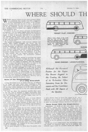
WHEN matters relative to the trend of future design are considered, they usually end with a suggestion for the re-positioning of the engine, or the redesign ing of that unit, with such an end in view. In practice, howeVer, conservatism has held sway both in this country and on the Continent, whereas, -in America, considerably more variation is to -be found, rear engines, in particular, 'being frequently used.
In defence of our own almost universal forward-control arrangement, with the engine slightly offset from the driver, and an orthodox type of vertically disposed six-cylindered engine, it must be generally admitted to be an efficient and practical layout evolved after years of development. Any new scheme, therefore, must provide an improvement on this well-tried layout if it is to find favour, and this will be by no means easy.
The present arrangement, with forward radiator and slightly offset engine alongside the driver, has the advantage that all components requiring adjustment are readily .accessible,, no efficiency being sacrificed in making them so. Although the front wings may prove to be a little awkward, they often provide a fairly good vantage point ,for the mechanic, but the practice,. of carrying a decorative fairing forward from the bulkhead, as is done on some vehicles, does not improve'matters, whilst, if the body be flush fronted, the accessibility problem
becomes really difficult._ . .
In such eases the easiest method of servicing the engine would be to draw it forward, through the front. It seems, too, that when decarbonising„ or conducting any other overhaul with the engine in position; that the tendency will be to place oily parts on the floor, or even on the seats, a procedure which is obviously undesirable.
This must be classed as a disadvantage of the flushfronted body because, although it is the ideal at which to aim from both the asthetic and aerodynamic points of view, such featUres must give place to more important mechanical de5iderata. A disadvantage of the orthodox model, however, is that the air is inspired into the cylinders after it has been heated by passage through the radiator, so that there is a reduction in volumetric efficiency with. a corresponding redaction in power output.
Some of the Disadvantages of a Long Drive-shaft A long drive-shaft, is by no means ideal for, in addition to its weight and cost, under some conditions a floor higher than would otherwise be necessary is called for. If the universal joints employed be of the metal type they sometimes become noisy and in any case require periodical lubrication. .
• To sum up, then, the maximum possible floor space is the aim, -and in securing it engine accessibility must not be sacrificed; -the engine compartment should not open into the passenger space, and the engine must not be
called upon to inspire heated air. ,
On the point of increased floor space, At, seems difficult to improve on the existing arrangement, and even on trolleybuses, where the motor is installed beneath the floor, there ia no marked increase in floor area. • If the rear-entrance type of body is to be retained, and the driver's position--unaltered, then the space at his side is all that
remains to be salvaged, .
On a double-deck vehicle the low floor required would, in all probability, prohibit the placing of seats in this position, as they would be over the wheel-arch, the height of which is governed by the allowance made for spring deflection, whilst the width is -controlled by the clearances. required for fully locked wheels. The width of the compartment thus formed is governed, on the one hand by the side wall and, on the other, by the driver's compartment wall, and, as the latter falls at approximately the centre line of the chassis it would be extremely difficult to provide access to two -side-by-side seats, even if the engine be placed elsewhere. If retained in the usual position it would be extremely inaccessihle.
As this space alongside the driver must be present, what is more obvious than to locate the engine in it? On a single-deck bus or coach, an arrangement worthy of consideration'wOuld be to move the front axle rearward and to place the passenger entrance forward of the front axle.
Some Scope With the Single-decker
Immediately in front of the axle there would be the driver, engine and entrance platform, the floor rearward being otherwise completely unobstructed and permitting the addition of at least two seats. If no door be fitted, the, driver would have excellent side visibility, and even if it be thought desirable to fit a door, suitable tramparent panels would help to retain the visibility feature. An important aspect of this scheme would be that the view which would be obtained by the driver would help materially in increasing tyre life, as it would permit him actually to see his position in relation to the kerb when
stopping. •. In. ttle case of the doable-decker, the rear-entrance body can hardly be improved upbn, for it is unlikely that sufficient spacewould be available beside the engine for the spacious platform essential to the quick loading and unloading of a dquble-deck bus. The stairway, too, would present a difficult problem, whilst the moving of the front , wheels rearward Would present difficulties to the body designer.
If the driver is to be retained in his present accepted position, it would appear that there is little that can be done, in the case of the normal double-decker, to increase the floor area, .but, as has been shown, Single-deck types offer some stope for improvement,
The Possibilities of Front-wheel Drive
With the orthodox type of engine located in the formal position, a method of eliminating the. drive shaft would be to use front-wheel drive, the engine, gearbox and final drive forming a unit. The suspension system might be of orthodox type, although, in order to clear the bevel or worm housing. some rather fierce bends. in the axle beam would have to be tolerated, The problem, however, is not insuperabh, as independent suspension, for example, is quite a possibility. In any case, here is all admirable opportunity to make the engine, transmission, front wheels and suspension as a unit, which could be quickly removed tor servicing. .
If the re-location of the driver were practicable, as was suggested by a writer in this journal some years ago, some saving in space might be practicable in that, if on a single _ decker the driver's compartment be elevated to roof height • or to upper-deck height oti a double-deck vehicle, then, assuming that a satisfactory position.. for the power unit could be found, the space made available could be utilized.
The possibilities, however, , are, again, more in favour of the single-decker, because, with this tyre, there is -no question of encroaching on top-deck space and the floor. height could be such that the front wheels Would not interfere with. passenger space. On the double-deck type it is doubtful if much increase of -passenger capacity could be achieved, as two seats Would have to be sacrificed to make room for the driver. On the other hand, it is certain that Such a driving positionwould greatly improve driving visibility.
The advantages of such a breakaway from conventional practice are more matters of actual trial than of conjecture; the new position would certainly cause considerable difficulty in the incorporation of the controls.
In view of the difficulties involved in effecting real improvements it would be as well analytically to examine some of the alternatives which have been put forward in the past. One of the best efforts made towards improving the orthodox without breaking entirely new ground was certainly to be found in the Leyland Gnu, in which model some slight increase in body space was achieved by locating the radiator at the side of the power unit, thus offering the possibility of inducing to it a cool air supply. As the engine is partly screened by the radiator, accessibility is certainly not improved, whilst the criticism applicable to a flush front, as previously referred to,,still applies. On the whole,. however, this arrangement would appear to be the best yet achieved Without a complete breakaway from what we recognize as -existing practice.
A Design Which Gave • Good Engine Accessibility
• The A.E.C. Q-type vehicle, which was of-novel design, *aroused great interest on its inception. As most readers will no doubt remember, the engine,. of standard type, was arrangedimmediately behind the off-side front wheel, overhanging the frame, an offset transmission system conveying the power to the rear wheels. In c'espect of space, little was gained on the single-deck model, in fact, rather the reverse, as the engine encroached into -the passenger space. -On the double-decker the stairway was so arranged that it passed overthe engine, the entrance platform being alongside the dEver and forward of the front axle.
As with all vehicles of this type, the driver was well situated for collecting fares on the less busy routes. Possibly the greatest advantage, however, was in the unparalleled engine accessibility which was gained, the removal of a side panel completelyexposing the unit.
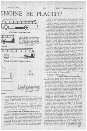
,Yet another arrangement which has been employed is to mount a more or less normal engine on its side, and to locaSe it amidships beneath the floor. The high floor which'irs required to give adequate road clearance must almost . ceitainly preclude this layout for double-deck vehicles, although it is entirely practicable for single. decker.' AocesSibility is hardly ideal, although the main components, no doubt, could be reached fairlyeasily from 'inside the coach. Apart from this, the only serious objection is that the radiator could scarcely be accommodated adjacent to the engine and, thus, long piping and a separate fan drive become necessary.
As it is hardly practicable to carry passengers alongside the driver, little advantage is to be-gained unless a front overhanging entrance be used and, as we have seen, this is probably practical evenwith an orthodox chassis. Some modifications would be required to the ,engine and these • would, include a new sump and carburetter or manifold
so that such a unit would not be interchangeable with other, models not so modified. .
The engine-at-the-rear idea has found much favour amongst builders in America, but justification for the system seems hard to find. In view of its length, longitudinal disposition of the unit is out of the question, so that a transverse position 'seems to be the only one possible. Here, again, accessibility is of a high order and leaves little to be desired. Even the transverse arrangement necessitates a considerable encroachment on passenger space, so that it will not compare for compactness with the other schemes reviewed.
The transmission layout is not all that might be desired, because, if a normal type of bevel-driven axle be required, a right-angle drive must be added to the rear end of the gearbox and, if the arrangement adopted by an American builder be considered, in which a spur-type final reduction gear is used, then outline bevels must be added to the gearbox.. This arrangement must be expensive, as the only saving achieved in drive-shaft cost is the little gained in shortening the tube, but there is the cost of the bevel box'.
Protagonists of this scheme suggest that decreased noise is attained, but this seems doubtful, fot the comparatively low speed of the vehicle can have little effect in leaving noise behind, and the mechanism is in as great a proximity to at least as many passengers as in the orthodox arrangement. In any case, it is the vibration which is transmitted through the frame which engenders discomfort rather than that which impinges on the ear drums.
Hydraulic Control Would Simplify Problems of Designer
Remote-control systems are not always easy of application, although, in the last case, a toil-Fe converter is fitted to. the elimination of the gear-change rod. The recent develOpment of hydraulic operation for the accelerator, and Similar controls, will do _ much to make the task of designing these items much lighter, and servicing troubles should not be unduly great, ‘,Thilst, if hydraulic brakes be fitted, a reservoir -common to all the controls is the obvious solution.
Discussion has so far centred about orthodox types of engine, but these may, of course,. be superseded or special units may even be. designed to meet specific layouts, so that attention -must be given to other power-unit types. The ttrizontally opposed, or " pancake," engine is an obvious possibility, and power units of this type have already' appeared on Tilling-Stevens chassis, whilst such a unit was a feature of the Henschel vehicle exhibited at a pre-war Earls Court Exhibition. Engines having 8 and 12 cylinders seem to be the most ,suitable, and there is
the possibility that the components,of standard fourand six-cylindered units may be utilized in the building up, of these types. A new location for the power, unit, which is feasible; is amidships, in which case the criticisms directed at under-floor engines, as previously put forward, still apply. One of the best arrangements was almost certainly that used on the German Henschel vehicle, in which the horizontally opposed 12-cylindered engine was slung beneath an upswept frame, forward of the front axle.
In this position, servicingis -an easy task, the cylinder -"heads being readily accessible, whilst if the injection pump, or pumps, be situated at the front of the engine and beneath the radiator, they, too, are readily getatable. When complete overhaul becomes necessary, it is an easy matter to release the holding-down bolts and, after sup,: porting-the engine, to wheel the vehicle away. The driver may, of course, be seated over the engine.
Unit Construction of Engine, Gearbox and Final Drive Another possible position for the I' pancake" engine is to carry it behind the rear axle—the unit being integral With the gearbox and final ,drive—and to transmit the drive to the wheels through universally jointed half-shafts: The wheels would be either independently suspended, or coupled by a large tube, in the form now known as the De Dion axle. Weight distribution, with this scheme, may cause some difficulty, but this matter could be dealt with only by consideration of individual vehicles and conditions.
Axial-cylindered engines of the " 2," or awash-plate type, have been referred to on many occasions by those outlining proposed schemes, but it is doubtful if they will be of much value' in improving the conditions of installation. Their large diameter would render under-floor fitting almost imposSible and if located at the front in the usual position no advantage would result. The radial engine offers some possibilities for either front or rea'r installation, although, if fitted at the rear, considerable space would be 'taken up, and even at the front the large diameter of such a unit may mean that the driver would have to be rpov,.ed rearward so that his controls, could be arranged behind the engine. If the engine were air cooled this would not be necessary, as the unit could take up the position now aCcupied„by the radiator.
It is hardly likely, however, that water cooling will be superseded. Owing to the height of the crankshaft, transfer gearing would almost certainly be necessary to bring the drive to a suitable level. By reason of its separate cylinders and water jackets the radial engine can hardly be considered a reasonable proposition for use in a commercial vehicle.