


Patents Completed.
Page 24
If you've noticed an error in this article please click here to report it so we can fix it.
PA N SION JOINT.--Christie.—No. 6,222, dated March 14th, 1906.—A s:eeve or barrel (a) receives the head (6) of the pipe connection (Oh and carried by the head is a cup-shaped washer (62) of metal or leather, secured in place by a nut. In the other end of the barrel a pipe connection (e c.1) is provided, and this, if desired, may also carry a cup-shaped washer. The parts are kept together by the nuts (g and It will be seen that the pressure of steam will expand the washer (0), and
at the same time the head (6) is free to move in the barrel without producing leakage.
STUFFING BOX. — Capitainee — No. 15,690, 1906, dated ender Convention, July 12th, 1905,—According to this iny-ention, a closing liquid is employed between the packing rings (C) of a gas engine, whereby escape of gas is prevented, and the arrangement of the apparatus is such that the liquid cannot be fed through to the cylinder (A) of the engine. The spring rings (C) surround the piston (11) in the usual manner, and an annular space (7.1 is provided, whereby the closing liquid from the chamber (El is admitted_ A plunger valve (E) is mounted in the chamber, and controlled by a spring (h), the forward end of this valve being in communication by a conduit (e) with the cylinder (A). In operation, the explosion in the cylinder forces back the plunger (E) until sufficient liquid has passed the valve (G) to the annular space (1) for the purpose of preventii g leakage. The movement of the valve is then prevented, because the space. between the iings is filled, and liquid cannot be forced into the cylinder, because the pressure there is somewhat greater than that prevailing amonest the packing rings, where a certain amount of leakage always occurs. Fresh quantities of liquid are admitted by the valve, and that which escapes from between the rings passes away by an annular space (P) and the conduit (S) ; the rings (R) prevent escape of liquid tothe outside of the engine.
RIVETED JOINT. — Hertwig,. — No. 26,087, 1905, dated, under Convention. December 19th, 1904.—According to this invention, a 'firm rivet is obtained by recessing the parts to be riveted as at 7, and
providing the head (2) with a similarly shaped lip. The tail portion of the rivet, when forged over, also enters the recess in the plate, and securely locks the two parts together.
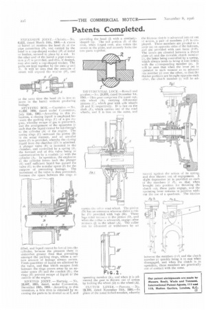
DIFFERENTIAL LOCK.--Burrell and another.—No. 24,978, dated December 1g, 1905.—This gear comprises the usual outside wheel (A), carrying differential pinions (Ce which gear with side wheels (D and E) respectively. D is fast on the shaft (F), which carries one of the road wheels, and E is free on the same, and carries the ether road wheel. The pinion (D) has an extension whereon slides a collar (G) provided with lugs (Ht. These lugs enter reciesss in the pinion (De and when the collar is advanced, engage other recesses di in the wheel (A). The collar can be advanced or withdrawn by an
operating member (K1, and when it is advanced the gear is thrown out of action by locking the wheel (D) to the wheel (A).
CLUTCH LEVER. — Parsons. -No. 23,180, dated November 11th, 1905.—In place of the usual forked member, whereby
the friction clutch is advanced into or out of action, a pair of members (i il) is employed. These members are pivoted to a lever 1m; on opposite sides of the fulcrum, rtnd are provided with cam faces (6 61). The levers are situated between a thrust plate (d) and the movable clutch membee (c), the latter being controlled by a spring, which always tends to bring it into action with the corresponding member (a). It will be seen that when the lever (m) is operated in such manner as to advance one member (i) over the other, so that the thicker portions are brought opposite each other, the clutch member (c) will be ad vanced against the action of its spring, and thus thrown out of engagement. A slight depression (a) is provided on each of the. members (i so that when brought into position for throwing the clutch out, these parts engage, and the operating lever remains in position without the use of a quadrant. The frictioa between the members (111) and the clutch member (c) quickly bring it to rest when disengaged, and when the clutch is in operation, these members are practically out of contact with the same.