AUTOMATIC SRM TO BE MADE BY GKN
Page 66

Page 67

If you've noticed an error in this article please click here to report it so we can fix it.
Modified SRM fully automatic transmission with five torque stages will be in full production by 1972.
by Paul Brockington, MI Mech E
THE SRM fully automatic two-stage torque converter gearbox is back in the news in modified form equipped with a two-speed synchromesh auxiliary gearbox that increases the number of torque stages available from three to five. It is equipped with a heat exchanger that is claimed to provide efficient control of oil temperatures and an hydraulic retarder control mechanism that gives smooth and progressive engagement.
GKN Birfield Transmission Ltd, Chester Road, Erdington, Birmingham 24, will produce the gearbox under licence to SRM Hydromechanik AB, Stockholm, Sweden, exclusively for the UK market and non exclusively for world markets including Sweden but excluding Italy. Following successful trials of the gearbox in the UK over a distance of some 30,000 miles, GKN has made plans to build 100 prototypes of the transmission for field testing by selected operators in 1971, and it is anticipated that it will have been "tooled-up" for full production in 1972.
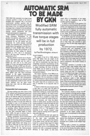
The test vehicle in current use is a ScaniaVabis 110S tractive unit coupled to a Peak tandem axle semi-trailer and the outfit is loaded for trial runs to its rated gross weight of 32 tons, the payload being 20 tons.
Developing 256 bhp at 2200 rpm. the turbocharged diesel engine produces its maximum torque of 788 lb ft at 1500 rpm.
The original mechanical gearbox was a 10speed splitter type with ratios accurately matched to the engine characteristics.
Initially, tests of the outfit were made with this transmission to obtain fuel consumptions and performance figures over selected routes so that comparisons could be made with the results obtained over the same routes during later trials with the SRM gearbox fitted to the unit.
Comparable fuel consumption
On long trunking runs with a driver of the GKN research and development department at the wheel, the SRM has enabled journey times to be reduced while fuel consumptions have been comparable. On the motorways the unit gives a more favourable fuel consumption by some 5 to 6 per cent which can be credited to lack of oil churning in the gearbox when the torque converter is locked up in the fifth high-range stage and the unit is operating without relative movement of the working parts. Although fuel consumption has been somewhat higher in faster urban traffic, the gain in journey times in such traffic is normally very substantial.
Initially, production will be concentrated on the DS 0.9 F,R,U transmission that is suitable for maximum outputs up to 300 bhp at 2500 rpm and the DS 0.75 F, R, Udesigned for higher speed diesels with ratings up to 250 bhp at 3400 rpm. In due course an uprated version of the 0.9 unit will be developed, suitable for the higher-powered engines required for vehicles in the 38/44
ton gvw category.
The weight of the 0.9 is 740Ib which is some 501b lighter than the weight of the Scania 10-speed box, while the cost of the unit will be considerably less than that of competitive automatic transmissions on the market. Of particular importance with regard to engine matching, the form of the converter blades can be varied to suit the particular characteristics of power units in the same general category.
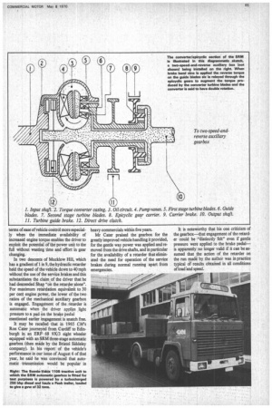
The torque converter of the SRM is unusual in that it affords two stages of torque multiplication with the minimum of complication and because it can be used as a retarder without employing additional mechanisms. The guide vanes (6) are carried on a rotor that is controlled by an epicyclic train of gears.
A sleeve to which the rotor is keyed carries a gear that is in mesh with the gears of the planet carrier (8) and if the carrier is prevented from rotating by a brake band (9) the reverse torque applied to the vanes is transmitted through the carrier gears to the output shaft (10). This is coupled to a shaft on the forward end of which the turbine of the converter is mounted, and when the planet carrier is locked about one-third of the total torque produced is relayed through the rotor and two-thirds through the turbine of the converter to give a maximum torque multiplication of 9.6 to 1. The gearbox is then operating in the "double rotation" stage which is used for starting and low-speed running under high load.
At a predetermined load and speed the action of a governor releases the brake band of the gear train controlling the guide-vane rotor, which permits free rotation of the planet carrier, and the rotor sleeve is locked by a second brake band (11) which holds the guide-vane rotor stationary. The converter then acts as a conventional (single rotation) unit with a consequent increase of efficiency at high speeds. In both these stages drive is transmitted in low range, that is with the underdrive ratio of the auxiliary gearbox engaged.
A clutch at the front of the gearbox (12) is mounted on a sleeve keyed to the converter turbine and engagement of the clutch locks the turbine to the pump (4). In the third stage the vane rotor is released, the converter is locked up and, as before, power is transmitted in low range. Direct drive of the auxiliary box is engaged for the fourth and fifth stages.
In the fourth stage the converter lock-up clutch is released, the vane rotor is locked and the converter operates as a single-rotation unit in high range. The converter is again locked up when the fifth (high range) stage is engaged.
The control can be set to "automatic low", "automatic high" and "automatic". In the automatic low range, operation of the gearbox is limited to the first three stages and this range is normally employed when the vehicle is descending steep gradients. Stages four and five are employed in the automatic high range together with a third stage (used for starting) in which direct drive of the auxiliary box is used in conjunction with double rotation of the converter.
Five-stage operation is provided in the automatic range, stage changes being made by the governor in the normal way in response to variations in speed and load, the control being such that it is impossible to over-rev the engine in any stage. A kick-down control is a standard fitting and provides changing down to a lower stage when the accelerator pedal is fully depressed given that the vehicle is running at a suitable speed. When the accelerator pedal is released, the converter automatically locks up to give engine braking and stays locked until vehicle speed has been reduced to about 10 mph.
Hydraulic retarder
The hydraulic retarder is of the "on-off" type and operates in the high and low ranges. When pressure is removed from the accelerator pedal the direct drive lock-up clutch is automatically engaged. The initial movement of the footbrake locks the planet carrier of the vane rotor control unit, so that the vanes rotate in the opposite direction to the converter driven by the epicyclic train, operation of the retarder being impossible if the accelerator pedal is depressed. The fluid of the converter system is cooled by a heat exchanger connected to the engine cooling system. Reverse gear is incorporated in the auxiliary gearbox.
Operation of the forward/neutral/reverse selector lever distributes air supplied by the vehicle " air reservoir to the appropriate hydraulic servo cylinder of the change-range system.
Having made a journey as a passenger around the Black Country and Birmingham in the cab of the Scania, the author can confirm that the gearbox is a boon in traffic in terms of ease of vehicle control more especially when the immediate availability of increased engine torque enables the driver to exploit the potential of the power unit to the full without wasting time and effort in gear changing.
In two descents of Mucklow Hill, which has a gradient of 1 in 9, the hydraulic retarder held the speed of the vehicle down to 40 mph without the use of the service brakes and this substantiates the claim of the driver that he had descended Shap "on the retarder alone". For maximum retardation equivalent to 30 per cent engine power, the lower of the two ratios of the mechanical auxiliary gearbox is engaged. Engagement of the retarder is automatic when the driver applies light pressure to a pad on the brake pedal mentioned earlier engagement is snatch free.
It may be recalled that in 1965 CM's Ron Cater journeyed from Cardiff to Edinburgh in an ERF 68 9X/3 eight wheeler equipped with an SRM three-stage automatic gearbox (then made by the Bristol Siddeley company). In his report of the vehicle's performance in our issue of August 6 of that year, he said he was convinced that automatic transmission would be popular in
heavy commercials within five years.
Mr Cater praised the gearbox for the greatly improved vehicle handling it provided, for the gentle way power was applied and removed from the drive shafts, and in particular for the availability of a retarder that eliminated the need for operation of the service brakes during normal running apart from emergencies. It is noteworthy that his one criticism of the gearbox—that engagement of the retard er could be "distinctly felt" even if gentle pressure were applied to the brake pedal— is apparently no longer valid if it can be assumed that the action of the retarder on the run made by the author was in practice typical of results obtained in all conditions of load 'and speed.


