


A Friction-type Servo Steering Gear
Page 36
If you've noticed an error in this article please click here to report it so we can fix it.
A Resume of Recently Published Patent Specifications
CERVO steering gear forms the sub.
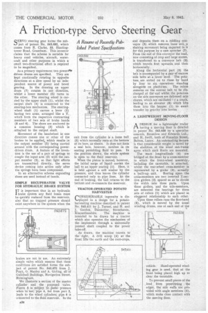
ject of patent No. 543,682, which comes from R. Clarke, 53, Huntingtower Road, Grantham. This inventor claims that the scheme is suitable for heavy road vehicles, aircraft, watercraft and other purposes in which a small two-directional effort is required to be magnified.
As a primary requirement two power44 driven drums are specified. They are kept continually rotating in opposite directions at a slow speed by an independent source of power and bevel gearing. In the drawing an upper drum (7) rotates in one direction, whilst a lower member (5) turns in the other. The steering wheel is carried by the upper shaft (1), whilst the output shaft (4) is connected to the steering-box mechanism. The steeringwheel shaft (1) carries a lever (2) having two arms, arranged like a Y, which form the respective contracting members of two sets of brake bands (8 and 6). The shoes are anchored to a common housing (3) which is attached to the output. shaft.
Movement of the handwheel in one direction causes one or other of the brakes to be applied, which results in the output member (3) being carried around with the corresponding power driven drum. A. feature of the invention is the use of a pair of springs to couple the input arm (2) with the output member (3), so that light efforts are transmitted directly. the servo device coming into action only after the springs have been compressed.
In an alternative scheme expanding 'shoes are used instead of hands.
SIMPLE RECUPERATOR VALVE FOR HYDRAULIC BRAKE SYSTEM I T is important that in an hydraulic brake system any fluid losses must be quickly replaced from the reservoir. also that no trapped pressure should exist anywhere in the system when the brakes are not in use. An extremely simple valve which ensures that these conditions a're satisfied forms the subject of patent No. 543,672 from J. Pratt, G. Manley and A. Girling, all of Guildhall Buildings, Navigation Street, Birmingham.
We illustrate a section of the master cylinder and the proposed Valve. Piston 3 is subject to pedal pressure. when in use; pipe 4, fed from port 2, leads to the wheel cylinders; pipe 6 is connected to the fluid reservoir. In the exit from the cylinder is a loose ball (5) which normally rests at the bottom of its bore, as shown. It does not form a seal here, however, notches in its seating permitting fluid to pass. In the position shown, the whole system is open to the fluid reservoir.
When the piston is moved, however, the initial surge of liquid carrieS the ball to an upper seating (1). Here, it is held against a soft washer by the pressure, and thus leaves the cylinder connected only to pipe lines. At the end of braking, the ball returns to the bottom and re-connects the reservoir.
TRACTOR•OPERATED POTATO HARVESTER
CONSIDERABLE ingenuity is displayed in a design for a potatoharvesting machine described in -patent No. 543,411 by J. Turner, and H. and J. Gordon, Dunnottar, Stonehaven, Kincardineshire. The machine is intended to be drawn by a' tractor which also operates the mechanism of the implement through a universally jointed shaft coupled to the power take-off.
As drawn, the machine travels to the right. A drill scoop (4) at the front lifts the earth and the root-crops,
and deposits them on a riddling conveyor (3) which removes loose soil, Ja shaking movement being imparted to it for this purpose by a-cam sprocket (7). From the end of this conveyor the load, now consisting of crop and large stones, is transferred to a conveyor belt (-2) which travels first upwards and then horizontally.
Along the horizontal part (5) the belt is accompanied by a pair of barrow side belts at a lower levelThe potatoes are sorted on to these by had by -four to six operatives standing alongside on platforms. The refuse re.mains on the central belt to be discharged at theend whilst the potatoes on the side conveyors are delivered into chutes, which are oscillated F y a crank, leading to an elevator (6) which lifts them into the hopper (1) to await transfer by gravity into lorries
A LIGHTWEIGHT MQVING-FLOOR DESIGN
ADESIGN for a lightweight trailer having a moving floor is detailed in patentNo. 543,658 by a specialist concern, Bromilow and Edwards Ltd., and FL Swift, both of Foundry Street, Bolton, Lancs. An outstanding feature is that considerable weight is saved by the abolition of the usual sub-frame upon which such floors are mounted.
The main longitudinals (4) are bridged at the front by a cross-member to which the front-wheel assembly,. including the turntable, is attached., whilst the rear-wheel cross-member is represented by a girder (3), actually
a built-up. unit. Resting upon the cross-members are two inverted T-section girders (2) spaced so as to divide the width into three parts. Upon these girders, and the side-members, are mounted the bearings for three sets of rollers (I) which are placed in staggered relationship to each other, . Upon these rollers runs the tloorband (6), which is moved by the usual winding drams, one at each end of the
vehicle. Hand-operated winding gear is used, that at the front being placed high up to clear the turntable.
To prevent small pieces of the load from penetrating the edges, the side walls are provided with angle members (5), which make close contact with the moving floor.